Electrical Engineering (EE) Exam  >  Electrical Engineering (EE) Test  >  Digital Electronics  >  Test: Combinational Logic - Electrical Engineering (EE) MCQ

Combinational Logic - Free MCQ Practice Test with solutions, GATE EE Digital


MCQ Practice Test & Solutions: Test: Combinational Logic (10 Questions)

You can prepare effectively for Electrical Engineering (EE) Digital Electronics with this dedicated MCQ Practice Test (available with solutions) on the important topic of "Test: Combinational Logic". These 10 questions have been designed by the experts with the latest curriculum of Electrical Engineering (EE) 2026, to help you master the concept.

Test Highlights:

  • - Format: Multiple Choice Questions (MCQ)
  • - Duration: 30 minutes
  • - Number of Questions: 10

Sign up on EduRev for free to attempt this test and track your preparation progress.

Test: Combinational Logic - Question 1

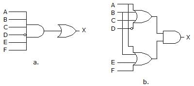
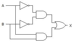
Which of the circuits in figure (a to d) is the sum-of-products implementation of figure (e)?

Detailed Solution: Question 1

SOP means Sum Of Products form which represents the sum of product terms having variables in complemented as well as in uncomplemented form. Here, the diagram of d contains the OR gate followed by the AND gates, so it is in SOP form.

Test: Combinational Logic - Question 2

The device shown here is most likely a ________

Detailed Solution: Question 2

The given diagram is demultiplexer, because it takes single input & gives many outputs. A demultiplexer is a combinational circuit that takes a single output and latches it to multiple outputs depending on the select lines.

Test: Combinational Logic - Question 3

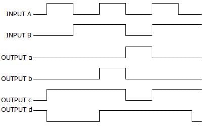
For a two-input XNOR gate, with the input waveforms as shown below, which output waveform is correct?

Detailed Solution: Question 3

When both inputs are same then the o/p is high for a XNOR gate.
i.e., A B O/P
0 0 1
0 1 0
1 0 0
1 1 1.
Thus, it will produce 1 when inputs are even number of 1s or all 0s, and produce 0 when input is odd number of 1s.

Test: Combinational Logic - Question 4

What is the indication of a short to ground in the output of a driving gate?

Detailed Solution: Question 4

Short to ground in the output of a driving gate indicates of a signal loss to all load gates. This results in information being disrupted and loss of data.

Test: Combinational Logic - Question 5

The carry propagation can be expressed as ________

Detailed Solution: Question 5

This happens in parallel adders (where we try to add numbers in parallel via more than one adders). A carry propagation occurs when carry from one adder needs to be forwarded to other adder and that second adder is holding the computation (addition) because carry from first adder has not come yet. So, there is a slight delay for second adder and this is known as carry propagation.

Test: Combinational Logic - Question 6

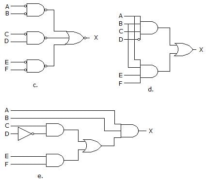
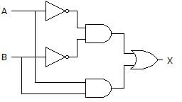
Which of the following logic expressions represents the logic diagram shown?

Detailed Solution: Question 6

1st output of AND gate is = A’B’
2nd AND gate’s output is = AB and,
OR gate’s output is = (A’B’)+(AB) = AB + A’B’.

Test: Combinational Logic - Question 7

What type of logic circuit is represented by the figure shown below?

Detailed Solution: Question 7

After solving the circuit we get (A’B’)+AB as output, which is XNOR operation. Thus, it will produce 1 when inputs are even number of 1s or all 0s, and produce 0 when input is odd number of 1s.

Test: Combinational Logic - Question 8

Which of the following combinations of logic gates can decode binary 1101?

Detailed Solution: Question 8

For decoding any number output must be high for that code and this is possible in One 4-input NAND gate, one inverter option only. A decoder is a combinational circuit that converts binary data to n-coded data upto 2n outputs.

Test: Combinational Logic - Question 9

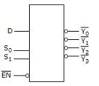
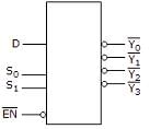
For the device shown here, assume the D input is LOW, both S inputs are LOW and the input is LOW. What is the status of the Y’ outputs?

Detailed Solution: Question 9

In the given diagram, S0 and S1 are selection bits. So,
I/P S0 S1 O/P
D = 0 0 0 Y0
D = 0 0 1 Y1
D = 0 1 0 Y2
D = 0 1 1 Y3
Hence, inputs are S0 and S1 are Low means 0, so output is Y0 and rest all are HIGH.

Test: Combinational Logic - Question 10

3 bits full adder contains ________

Detailed Solution: Question 10

Full Adder is a combinational circuit with 3 input bits and 2 output bits CARRY and SUM. Three bits full adder requires 23 = 8 combinational circuits.

113 videos|91 docs|58 tests
Information about Test: Combinational Logic Page
In this test you can find the Exam questions for Test: Combinational Logic solved & explained in the simplest way possible. Besides giving Questions and answers for Test: Combinational Logic, EduRev gives you an ample number of Online tests for practice
113 videos|91 docs|58 tests
Download as PDF