Mechanical Engineering Exam  >  Mechanical Engineering Tests  >  Design of Machine Elements  >  Test: Design of Joints Level - 3 - Mechanical Engineering MCQ

Test: Design of Joints Level - 3 - Mechanical Engineering MCQ


Test Description

20 Questions MCQ Test Design of Machine Elements - Test: Design of Joints Level - 3

Test: Design of Joints Level - 3 for Mechanical Engineering 2024 is part of Design of Machine Elements preparation. The Test: Design of Joints Level - 3 questions and answers have been prepared according to the Mechanical Engineering exam syllabus.The Test: Design of Joints Level - 3 MCQs are made for Mechanical Engineering 2024 Exam. Find important definitions, questions, notes, meanings, examples, exercises, MCQs and online tests for Test: Design of Joints Level - 3 below.
Solutions of Test: Design of Joints Level - 3 questions in English are available as part of our Design of Machine Elements for Mechanical Engineering & Test: Design of Joints Level - 3 solutions in Hindi for Design of Machine Elements course. Download more important topics, notes, lectures and mock test series for Mechanical Engineering Exam by signing up for free. Attempt Test: Design of Joints Level - 3 | 20 questions in 60 minutes | Mock test for Mechanical Engineering preparation | Free important questions MCQ to study Design of Machine Elements for Mechanical Engineering Exam | Download free PDF with solutions
Test: Design of Joints Level - 3 - Question 1

Assertion (A): Uniform-strength bolts are used for resisting impact loads.

Reason (R): The area of cross-section of the threaded and unthreaded parts is made equal

Detailed Solution for Test: Design of Joints Level - 3 - Question 1

Uniform-strength bolts are used for resisting impact loads as these bolts have more strain energy storing capacity.

⇒The area of cross-section of the threaded and unthreaded portion is made equal to increase the strain energy storing capacity.

Test: Design of Joints Level - 3 - Question 2

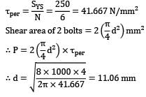
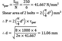
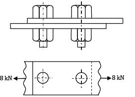
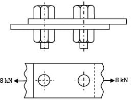
Two plates are joined together using two bolts as shown in figure. The shear strength in yield for the bolt material is N mm . Taking a factor of safety of 6, the diameter of the bolt is
Detailed Solution for Test: Design of Joints Level - 3 - Question 2

1 Crore+ students have signed up on EduRev. Have you? Download the App
Test: Design of Joints Level - 3 - Question 3

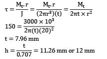
A circular shaft, 40 mm in diameter, is welded to the support by means of circumferential fillet weld. It is subjected to a torsional moment of 3000 Nm. Permissible shear stress in weld is limited to N mm . The size of weld is

Detailed Solution for Test: Design of Joints Level - 3 - Question 3

Torsional shear stress in the weld

t = 7.96 mm

*Answer can only contain numeric values
Test: Design of Joints Level - 3 - Question 4

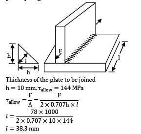
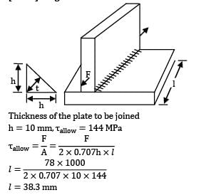
A plate 50 mm wide and 10 mm thick is to be welded as T joint to another plate by means of two parallel fillet welds. If the plates are subjected to a static load of 78 kN and the allowable shear stress is 144 MPa. The weld length per side (in mm


Detailed Solution for Test: Design of Joints Level - 3 - Question 4

Thickness of the plate to be joined

h = 10 mm,τallow = 144 MPa

l = 38.3 mm

*Answer can only contain numeric values
Test: Design of Joints Level - 3 - Question 5

A steel plate 200 mm wide and 5 mm thick is welded with another steel plate as shown in figure. The permissible tensile and shear stresses for the weld material are 80 MPa and 60 MPa respectively. If the plates can withstand a load upto 80 kN, then the ratio of the strength of transverse fillet weld to the double parallel fillet weld is __________


Detailed Solution for Test: Design of Joints Level - 3 - Question 5

Let, P1 = Strength of transverse fillet weld

P2 = Strength of double parallel fillet weld

Now, P1 = 0.707 (hl t)

= 0.707 x 5 x 200 x 60

= 42420 N

Now, P = P1 + P2

P2 = P - P1 = 80000 - 42420 = 37580 N

Test: Design of Joints Level - 3 - Question 6

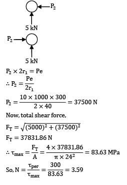
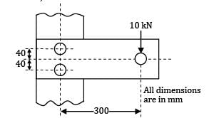
A bracket shown in the figure is bolted to a column using two bolts. If the permissible shear stress of the bolt material is 300 MPa, then the factor of safety is ( a ing d mm)
Detailed Solution for Test: Design of Joints Level - 3 - Question 6

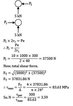
P2 x 2r1 = Pe

Now, total shear force,

FT = 37831.86 N

Test: Design of Joints Level - 3 - Question 7

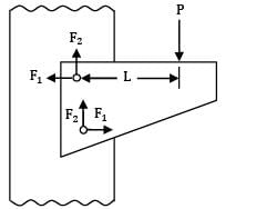
A riveted joint has been designed to support an eccentric load P. The load generates value of equal to 4 kN and equal to 3 kN. The cross-sectional area of each rivet is mm . Consider the following statements

1. The stress in the rivet is N mm

2. The value of eccentricity L is 100 mm

3. The value of load P is 6 kN

4. The resultant force in each rivet is 6 kN Which of these statements are correct?
Detailed Solution for Test: Design of Joints Level - 3 - Question 7

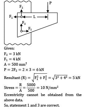
Given:

F2 = 3 kN

F1 = 4 kN

A = 500 mm2

P = 2F2 = 2 x 3 = 6 kN

Eccentricity cannot be obtained from the above data.

So, statement 1 and 3 are correct.

Test: Design of Joints Level - 3 - Question 8

For the figure shown below, the permissible tensile and shear stresses for the weld material and plates are N mm and N mm . If the depth of weld is 15 mm, the length of each parallel fillet weld is

Detailed Solution for Test: Design of Joints Level - 3 - Question 8

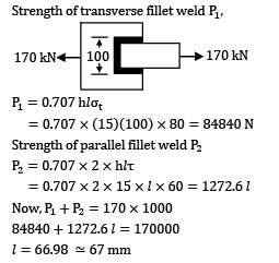
Strength of transverse fillet weld P1

P1 = 0.707 hl t

= 0.707 x (15)(100) x 80 = 84840 N

Strength of parallel fillet weld P2

P2 = 0.707 x 2 x hlτ

= 0.707 x 2 x 15 x l x 60 = 1272.6 l

Now, P1 + P2 = 170 x 1000

84840 + 1272.6 l = 170000

l = 66.98 mm

Test: Design of Joints Level - 3 - Question 9

A bracket is welded to the vertical plate by means of two fillet welds as shown in figure. The stresses induced in the weld are

Detailed Solution for Test: Design of Joints Level - 3 - Question 9

The load is transverse shear load and it will induce shear force and a bending moment.

Test: Design of Joints Level - 3 - Question 10

Two plates, 25 mm thick, are welded together by means of a reinforced butt weld and subjected to a completely reversed axial load of 土100kN as shown in figure. The throat of the weld is 25 mm. The ultimate tensile strength of the weld metal is 450N/mm2. The surface finish of the weld is equivalent to that of forged component and the reliability is 90%. The length of the weld is

[Assume factor of safety is 2.

Detailed Solution for Test: Design of Joints Level - 3 - Question 10

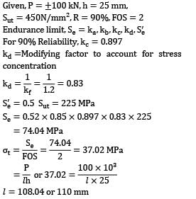
Given, P = kN, h = 25 mm

Sut = 450N/mm2, R = 90%, FOS = 2

Endurance limit, Se = ka,kb,kc,kd,S’e

For 90% Reliability,kc = 0.897

kd = Modifying factor to account for stress concentration

S’e = 0.5 Sut = 225 MPa

Se = 0.52 x 0.85 x 0.897 x 0.83 x 225

= 74.04 MPa

l =108.04 or 110 mm

Test: Design of Joints Level - 3 - Question 11

A circular beam, 50 mm in diameter, is welded to a support by means of a fillet weld as shown in figure. The size of the weld, if the permissible shear stress in the weld is limited to 100N/mm2, is (in mm)

Detailed Solution for Test: Design of Joints Level - 3 - Question 11

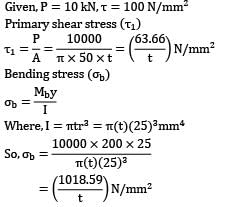
Given, P = 10 kN,T = 100 N/mm2

Primarily shear stress (T1)

Bending stress ( b)

Where, I = πtr3 = π(t)(25)3mm4

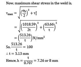
Now, maximum shear stress in the weld is;

∴ t = 5.13 mm

Test: Design of Joints Level - 3 - Question 12

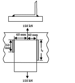
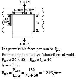
A bracket, as shown in figure, is welded to a plate. The welds are of same size

The value of permissible force per mm of the weld length is
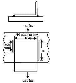
Detailed Solution for Test: Design of Joints Level - 3 - Question 12

Let permissible force per mm be Pper

From moment equality of shear force at weld

Pper x 50 x 60 = Pper x l2 x 40

l2 = 75 mm

*Answer can only contain numeric values
Test: Design of Joints Level - 3 - Question 13

A bracket is welded to the vertical plate by means of two fillet welds as shown in the fig. If the permissible shear stress is limited to 55N/mm2 . The size of weld is __________ (mm)
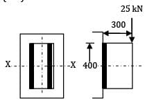

Detailed Solution for Test: Design of Joints Level - 3 - Question 13

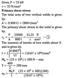
Given, P = 25 kN

T = 55 N/mm2

Primary shear stress

The total area of two vertical welds is given by,

A = 2(400 t) = (800 t) mm2

The primary shear stress in the weld is given by,

The moment of inertia of two welds about Xaxis is given by,

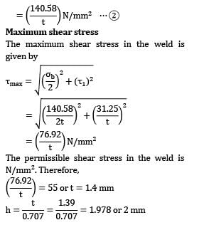
Maximum shear stress

The maximum shear stress in the weld is given by

The permissible shear stress in the weld is N/mm2. Therefore,

Test: Design of Joints Level - 3 - Question 14

In the figure a plate is connected to another plate by fillet welds around the ends and also inside the machined slot. The working stresses for the transverse welds and longitudinal welds are. 102.5 MN/m2 and 84MN/m2 respectively. If joint is subjected to a pull of 100 kN, the size of weld will be
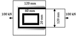
Detailed Solution for Test: Design of Joints Level - 3 - Question 14

Length of longitudinal weld,

l = (2 x 120) + (2 x 60) = 360 mm

Length of transverse weld = 120 + 2 x 20

= 160 mm

s = size of weld

∴Effective thickness of weld

t = 0.707 s

Using the relation P = lt

P1 = 360 x 0.707 s x 10-6 x 84 x 106

= 21379 s

Similarly

P2 = 160 x 0.707 s x 10-6 x 102.5 x 106

11595

Total force of resistance of the welds

P = P1 + P2

= 21379 s + 11595 s

= 32974 s

Now, P = 100 x 103 N

100 x 103 = 32974 s

s = 3.03 3 mm

Test: Design of Joints Level - 3 - Question 15

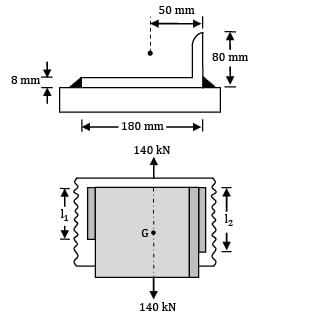
An mm angle is welded to a steel plate by means of fillet-welds as shown in the figure. The angle is subjected to a static load of 140 kN, which passes through the center of gravity G and the allowable load per mm of the weld length is 700 N. The length of the shorter fillet weld is
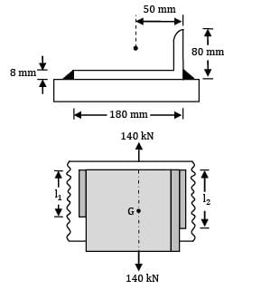
Detailed Solution for Test: Design of Joints Level - 3 - Question 15

Total length of weld (l),

Let the resisting forces, setup in the welds 1 and 2 be P1 and P2

P1 = 0.707 hl1T,P2 = 0.707 hl2T

The moment of about G should be 0.

∴ P1r1 = P2r2

l1r1 = l2r2

Also, l1 + l2 = I = 200 mm

l1 x 130 = l2 x 50

L2 = 2.611

L1 = 55.56 mm and l2 = 144.44 mm

Test: Design of Joints Level - 3 - Question 16

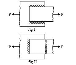
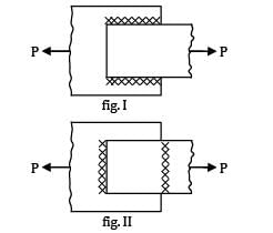
The following two figures show welded joints (x x x x x indicates welds), for the same load and same dimensions of plate and weld.

The joint shown in
Detailed Solution for Test: Design of Joints Level - 3 - Question 16

Figure II is better because the weld is in tension and safe stress of weld in tension is greater than shear.

Test: Design of Joints Level - 3 - Question 17

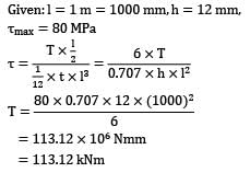
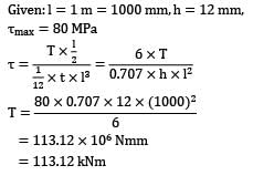
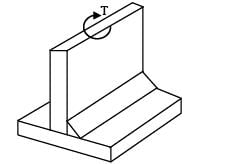
A plate 1 m long, 70 mm thick is welded to another plate at right angles to each other by 12 mm fillet weld, as shown in the figure. What is the maximum torque T, that the welded joint can sustain if the permissible shear stress intensity in the weld is not exceed to 80 MPa.
Detailed Solution for Test: Design of Joints Level - 3 - Question 17

Test: Design of Joints Level - 3 - Question 18

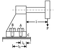
A cast iron bracket, supporting the transmission shaft and the belt pulley, is fixed to the steel structure by means of four bolts as shown in Fig. There are two bolts at

A and two bolts at

B. The tensions in slack and tight sides of the belt are 5 kN and 10 kN respectively. The belt tensions act in a vertically downward direction. The distances are as follows,

l1 = 50 mm, l2 = 150 mm, l = 200 mm The maximum permissible tensile stress in any bolt is 60 N/mm2 . Determine the size of the bolts (in mm2 )
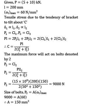
Detailed Solution for Test: Design of Joints Level - 3 - Question 18

Given,P = (5 + 10) kN,

l = 200 mm

t)max = 60 N/mm2

Tensile stress due to the tendency of bracket to tilt about ‘C’

P1= Cl1, P2 = Cl2

Pl = 2P1l1 + 2P2l2 = 2(Cl1)l1 + 2(Cl2)l2

The maximum force will act on bolts denoted by 2

P2 = Cl2

Size of bolts, P2 = A( t)max

9000 = A(60)

∴A = 150 mm2

Test: Design of Joints Level - 3 - Question 19

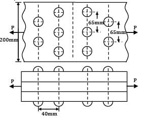
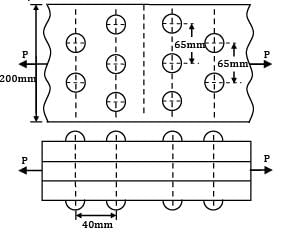
Two flat plates subjected to a tensile force p are connected together by means of 25 mm diameter rivets with double strap butt joint as shown.

The thickness of plate is 25 mm and plate width is 200 mm. Rivets and plates are made of same material and having following properties.τper.= 60 MPa, (σt) = 70 MPa, (σc)per= 100 MPa What is the efficiency of the joint?
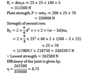
Detailed Solution for Test: Design of Joints Level - 3 - Question 19

Given, w = 200 mm, t = 70 MPa, c = 100 MPa

d = 25 mm,T =60 MPa, N =

= 294524.31 N

Pt1 = (w - 2d)t, t = (200 - 2 x 25)25 x 70

= 262500 N

Pc = dtσcn 25 x 25 x 100 x 5

312500 N

Plate strength, P = wtσt 200 x 25 x 70

= 350000 N

Strength of second row,

X 25 x 70

= 117809.7 + 218750 = 336559.7 N

∵ Lowest strength = 262500 N

Efficiency of the joint is given by,

Test: Design of Joints Level - 3 - Question 20

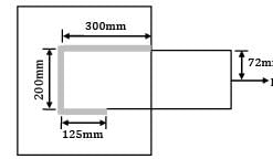
A steel plate is joined with another plate using weld fillet as shown in the figure. If the permissible shear stress of weld material is 50 N/mm2 and leg of the weld is 10 mm, what could be the maximum value of P?
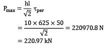
Detailed Solution for Test: Design of Joints Level - 3 - Question 20

There will be primary shear stress due to P and secondary shear stress due to moment.

Center of gravity of fillet weld from upper length

As P is applied exactly at center of gravity of fillet weld, there won’t be any moment.

= 220.97 kN

49 videos|70 docs|77 tests
Information about Test: Design of Joints Level - 3 Page
In this test you can find the Exam questions for Test: Design of Joints Level - 3 solved & explained in the simplest way possible. Besides giving Questions and answers for Test: Design of Joints Level - 3, EduRev gives you an ample number of Online tests for practice

Top Courses for Mechanical Engineering

49 videos|70 docs|77 tests
Download as PDF

Top Courses for Mechanical Engineering