1 Crore+ students have signed up on EduRev. Have you? Download the App |
A diode rectifier cannot perform rectification in both directions' is a perfect example of:
Unilateral Circuit:
In comparing the operation of the half-controlled 2-pulse circuit with that of the fully-controlled circuit, which of the following statements are evident?
1. Since half the thyristors are replaced by diodes, a half-controlled converter costs less than a fully-controlled converter.
2. Due to the freewheeling action with a half-controlled bridge-circuit power factor is improved in half-controlled converters.
3. The AC supply current is more distorted due to its zero periods with the half-controlled circuit, compared to a fully-controlled bridge circuit.
Select the correct answer using the code given below :
Difference Between Half Wave and Full Wave Rectifier:
The average current rating of a semiconductor diode will be maximum for:
Maximum Average Forward Current (IFAVM):
Diodes are often used in rectifier circuits supplying a DC (average) current to the load.
In such cases, the average load current and the diode forward current usually have a simple relationship.
Therefore, it will be of interest to know the maximum average current, a diode can conduct in the forward direction.
This specification gives the maximum average value of power frequency half cycle sine wave current allowed to flow through the diode in the forward direction.
The average current rating of a diode decreases with a reduction in conduction angle due to an increase in the current “form factor”.
Full-wave rectifier output waveform:
Average current value = 2Im/π
Half-wave rectifier output waveform:
Average current value = Im/π
DC output waveform:
Average current value = Im
So average current rating will be in the order of DC > Full-wave rectifier > Half-wave rectifier.
Ripple factor:
The amount of AC present in the output of the signal is called as ripple.
The ripple factor indicates the number of ripples present in the DC output.
The output of the power supply is given by
It is given as:
Thus if the ripple factor is less, the power supply has less AC components and power supply output is purer (i.e more DC without much fluctuations)
Thus ripple factor is an indication of the purity of output of the power supply.
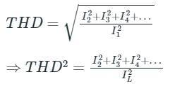
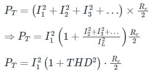
For a total harmonic distortion of 0.1 with I1 = 4A and Rc = 8Ω, calculate total power
Concept:
Total harmonics distortion is given by,
Now, total power due to all harmonic component
Calculation:
Given that, THD = 0.1
IL = 4 A, Rc = 8 Ω
⇒ PT = (4)2(1 + (0.1)2) × 8/2
PT = 64.64 W
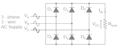
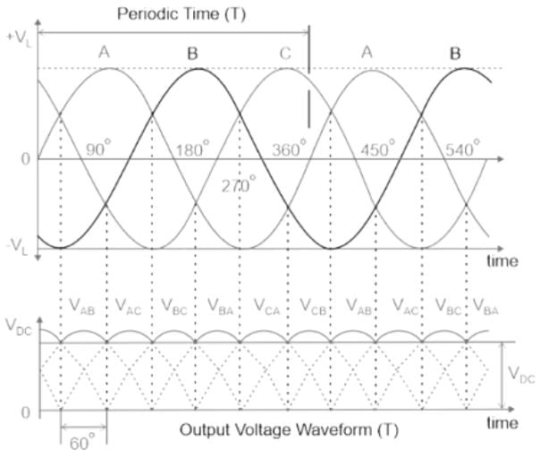
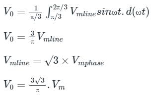
Average output voltage of a three-phase full wave diode rectifier is given by:
Three-Phase Full Wave Diode Rectifier:
Calculate the rectification efficiency of half wave rectifier if input power to rectifier is 150 W and power obtained is 90 W.
Formula Used:
efficiency (%η) = Po/Pi
Here, Po is the output power
And, Pi is the input power
Application:
Given,
Input AC Power (Pi) = 150 W
Output DC Power (Po) = 90 W
Hence, Efficiency (η) = 90/150 = 0.6 = 60 %
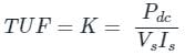
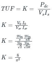
The transformer Utilization factor of a bridge rectifier is approximately:
Transformer Utilization Factor (TUF):
It is defined as the ratio of dc power output to the transformer Volt-Ampere (VA) rating required by the secondary winding.
TUF = (DC power output) / (Effective VA rating of transformer)
It is a quantitative indication of the utilization of the VA Rating of Transformer. The more the value of TUF, the more will be the utilization. In other words, the VA rating of the required transformer will be less if TUF is more and vice versa.
Application:
Considering R load,
The output average voltage of a single-phase full-bridge diode rectifier is given by
V0 = 2Vm/π
Here, The output average current for R load is given by
Supply voltage Vs RMS is given by Vm/√2
Supply current Is RMS is given by
Now,
= 0.81
= 81%
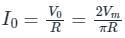
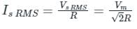
A single-phase full wave bridge diode rectifier delivers a constant current of 10 A to the load. Average and RMS values of source current are
Concept:
In a single-phase uncontrolled diode rectifier
The average output voltage, Vo = 2Vm/π
Supply RMS current isr = Io
Supply average current = 0
In a three-phase uncontrolled diode rectifier
The average output voltage, Vo = 3Vml/π
Supply RMS current isr =
Supply average current = 0
Calculation:
Given that, load current (I0) = 10 A
Supply average current = 0 A
Supply RMS current = 10 A
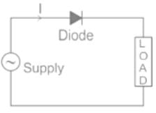
In the process of diode based rectification, the alternating input voltage is converted into
Rectification is AC to DC. In DIODE biased rectification, control is not possible.
5 videos|39 docs|63 tests
|
5 videos|39 docs|63 tests
|