Electrical Engineering (EE) Exam  >  Electrical Engineering (EE) Tests  >  Engineering Services Examination (ESE) Mock Test Series 2024  >  Test: ESE Electrical - 9 - Electrical Engineering (EE) MCQ

Test: ESE Electrical - 9 - Electrical Engineering (EE) MCQ


Test Description

30 Questions MCQ Test Engineering Services Examination (ESE) Mock Test Series 2024 - Test: ESE Electrical - 9

Test: ESE Electrical - 9 for Electrical Engineering (EE) 2024 is part of Engineering Services Examination (ESE) Mock Test Series 2024 preparation. The Test: ESE Electrical - 9 questions and answers have been prepared according to the Electrical Engineering (EE) exam syllabus.The Test: ESE Electrical - 9 MCQs are made for Electrical Engineering (EE) 2024 Exam. Find important definitions, questions, notes, meanings, examples, exercises, MCQs and online tests for Test: ESE Electrical - 9 below.
Solutions of Test: ESE Electrical - 9 questions in English are available as part of our Engineering Services Examination (ESE) Mock Test Series 2024 for Electrical Engineering (EE) & Test: ESE Electrical - 9 solutions in Hindi for Engineering Services Examination (ESE) Mock Test Series 2024 course. Download more important topics, notes, lectures and mock test series for Electrical Engineering (EE) Exam by signing up for free. Attempt Test: ESE Electrical - 9 | 150 questions in 180 minutes | Mock test for Electrical Engineering (EE) preparation | Free important questions MCQ to study Engineering Services Examination (ESE) Mock Test Series 2024 for Electrical Engineering (EE) Exam | Download free PDF with solutions
Test: ESE Electrical - 9 - Question 1

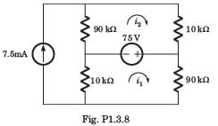
i1 = ?

Detailed Solution for Test: ESE Electrical - 9 - Question 1


Test: ESE Electrical - 9 - Question 2

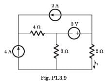
i1 = ?

Detailed Solution for Test: ESE Electrical - 9 - Question 2

1 Crore+ students have signed up on EduRev. Have you? Download the App
Test: ESE Electrical - 9 - Question 3

Find the value of Vx due to the 16V source.​

Detailed Solution for Test: ESE Electrical - 9 - Question 3

When we consider the 16V source, we short the 10V source and open the 15A and 3A source. From the resulting series circuit we can use voltage divider to find Vx.
Vx = 16*20/(20+80) = 3.2A.

Test: ESE Electrical - 9 - Question 4

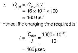
The charging time required to charge the equivalent capacitance between the given terminals a-b by a steady direct current of constant magnitude of 10 A is given by:
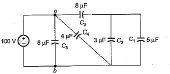
Detailed Solution for Test: ESE Electrical - 9 - Question 4

Equivalent capacitance between terminals a-b is:

Test: ESE Electrical - 9 - Question 5

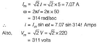
 An ac voltage of 220 V is applied to a pure inductance of 50 H. If the current is 5 A, the instantaneous value of voltage and current will be respectively given by:

Detailed Solution for Test: ESE Electrical - 9 - Question 5

Max. value of current:

Assuming voltage as the reference phasor:

Test: ESE Electrical - 9 - Question 6

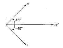
The voltage and current through a circuit element is v = 100 sin (314 t + 45°) volts and i = 10 sin (314 t - 45°) amps.
The type of circuit element and its value will be respectively:

Detailed Solution for Test: ESE Electrical - 9 - Question 6

The phase difference between v and i is: 

Since v leads i therefore, the circuit element is an inductor.

Test: ESE Electrical - 9 - Question 7

Determine the complex power for hte given values in question.

Vrms = 220 V, P = 1 kW, |Z| = 40Ω (inductive)  

Detailed Solution for Test: ESE Electrical - 9 - Question 7


 = 0.8264 or θ = 34.26°,

Test: ESE Electrical - 9 - Question 8

h21 = ?

Detailed Solution for Test: ESE Electrical - 9 - Question 8

Test: ESE Electrical - 9 - Question 9

In wye or star connection _____________ of the three phases are joined together within the alternator.

Detailed Solution for Test: ESE Electrical - 9 - Question 9

In wye or star connection, similar ends of the three phases are joined together within the alternator. The common terminal so formed is referred to as the neutral point or neutral terminal.

Test: ESE Electrical - 9 - Question 10

The three impedances Z1 = 20∠30⁰Ω, Z2 = 40∠60⁰Ω, Z3 = 10∠-90⁰Ω are delta-connected to a 400V, 3 – Ø system. Find the phase current IB.

Detailed Solution for Test: ESE Electrical - 9 - Question 10

The voltage VBR is VBR = 400 ∠ -240⁰V. The impedance Z3 is Z3 = 10 ∠ -90⁰Ω
⇒ IB = (400 ∠ 240o)/(10 ∠ -90o) = (-34.64-j20)A.

Test: ESE Electrical - 9 - Question 11

Calculate the emf when the flux is given by 3sin t + 5cos t

Detailed Solution for Test: ESE Electrical - 9 - Question 11

The electromotive force is given by Vemf = -dλ/dt. Thus Vemf = -dλ/dt = -(3cos t – 5sin t) = -3cos t + 5sin t.

Test: ESE Electrical - 9 - Question 12

Calculate the emf when a coil of 100 turns is subjected to a flux rate of 0.3 tesla/sec.

Detailed Solution for Test: ESE Electrical - 9 - Question 12

The induced emf is given by Vemf = -dλ/dt = -Ndψ/dt. Thus emf will be -100 x 0.3 = -30 units.

Test: ESE Electrical - 9 - Question 13

Which of the following is done to convert a continuous time signal into discrete time signal?

Detailed Solution for Test: ESE Electrical - 9 - Question 13

A discrete time signal can be obtained from a continuous time signal by replacing t by nT, where T is the reciprocal of the sampling rate or time interval between the adjacent values. This procedure is known as sampling.

Test: ESE Electrical - 9 - Question 14

The Nth root of unity WN is given as: 

Detailed Solution for Test: ESE Electrical - 9 - Question 14

We know that the Discrete Fourier transform of a signal x(n) is given as

Thus we get Nth rot of unity WN= e-j2π/N

Test: ESE Electrical - 9 - Question 15

Which of the following is true regarding the number of computations requires to compute an N-point DFT? 

Detailed Solution for Test: ESE Electrical - 9 - Question 15

The formula for calculating N point DFT is given as

From the formula given at every step of computing we are performing N complex multiplications and N-1 complex additions. So, in a total to perform N-point DFT we perform N2 complex multiplications and N(N-1) complex additions.

Test: ESE Electrical - 9 - Question 16

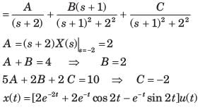
Determine the time signal x(t) corresponding to given X (s) and choose correct option.
 

Detailed Solution for Test: ESE Electrical - 9 - Question 16


Test: ESE Electrical - 9 - Question 17

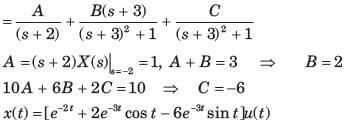
Determine the time signal x(t) corresponding to given X (s) and choose correct option.
 

Detailed Solution for Test: ESE Electrical - 9 - Question 17


Test: ESE Electrical - 9 - Question 18

Determine the Fourier series coefficient for given periodic signal x(t).

x(t) as shown in fig. P5.7.3
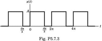
Detailed Solution for Test: ESE Electrical - 9 - Question 18


Test: ESE Electrical - 9 - Question 19

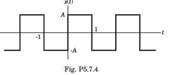
Determine the Fourier series coefficient for given periodic signal x(t).

x(t) as shown in fig. P5.7.4
Detailed Solution for Test: ESE Electrical - 9 - Question 19


Test: ESE Electrical - 9 - Question 20

Consider a continuous time periodic signal x(t) with fundamental period T and Fourier series coefficients X[k]. Determine the Fourier series coefficient of the signal y(t) given in question and choose correct option.

y(t) = Ev{x(t)}

Detailed Solution for Test: ESE Electrical - 9 - Question 20


The FS coefficients of x(t) are


Therefore, the FS coefficients of Ev{ x(t)} are

Test: ESE Electrical - 9 - Question 21

A sinusoid x(t) of unknown frequency is sampled by an impulse train of period 20 ms. The resulting sample train is next applied to an ideal lowpass filter with cutoff at 25 Hz. The filter output is seen to be a sinusoid of frequency 20 Hz. This means that x(t) is

Detailed Solution for Test: ESE Electrical - 9 - Question 21

Period of sampling train, Ts = 20 ms

If frequency of x(t) is fx, then after sampling the signal, the sampled signal has the frequency,
fs - fx = 50 - fx and fs + fx = 50 + fs
Now, the sampled signal is applied to and ideal low pass filter with cut off frequency.
fc = 25 Hz
Now, the o/p of filter carried a single frequency component of 20 Hz
∴, only (fs−fx) component passes through the filter, ie.
fs - fx < 25
and fs - fx = 20
50 - fx­ = 20
fx = 50 - 20 = 30 Hz

Test: ESE Electrical - 9 - Question 22

The following butterfly diagram is used in the computation of:

Detailed Solution for Test: ESE Electrical - 9 - Question 22

The above given diagram is the basic butterfly computation in the decimation-in-time FFT algorithm.

Test: ESE Electrical - 9 - Question 23

Which of the following equation is true?

Detailed Solution for Test: ESE Electrical - 9 - Question 23

We know that,

Test: ESE Electrical - 9 - Question 24

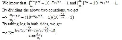
What is the order N of the low pass Butterworth filter in terms of KP and KS?

Detailed Solution for Test: ESE Electrical - 9 - Question 24

Test: ESE Electrical - 9 - Question 25

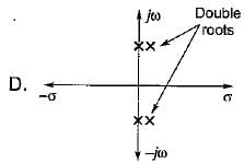
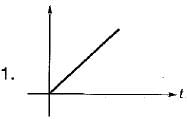
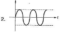
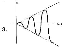
Match List - I (Roots in s-plane) with List - II (Corresponding impulse response) and select the correct answer using the codes given below the lists:
List - I
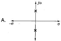
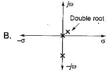
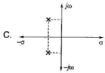
List - II
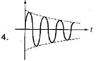
Codes:
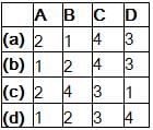
Detailed Solution for Test: ESE Electrical - 9 - Question 25

For A: Two conjugate poles on imaginary axis i.e. it’s impulse response = sin at (marginally stable).
For B: Two poles at origin i.e. impulse response = t u(t) (unstable system).
For C: Two complex conjugate poles with negative real parts. So, its impulse response = er-at sin bt (stable system).
For D: Two imaginary complex double roots. So, impulse response = t sin bt. (unstable system).

Test: ESE Electrical - 9 - Question 26

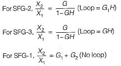
Consider the following three cases of signal flow graph and their corresponding transfer functions:
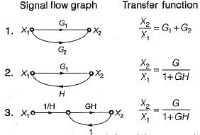
Q. Which of the above relations is/are correctly matched?

Detailed Solution for Test: ESE Electrical - 9 - Question 26


Hence, only 1 is correctly matched.

Test: ESE Electrical - 9 - Question 27

The peak overshoot of step-input response of an underdamped second-order system is an indication of

Detailed Solution for Test: ESE Electrical - 9 - Question 27

If damping of system increases, peak overshoot Mp decreases and vice-versa.

Test: ESE Electrical - 9 - Question 28

Consider the following statements regarding the characteristic equation of a system given by:
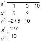
s4 + 5s3 + 25+10 = 0

  1. The system is unstable.
  2. The system is stable.
  3. Number of roots with zero real part - 0
  4. Number of roots with positive real part - 4
  5. Number of roots with negative real part = 2

Which of the above statements are correct?

Detailed Solution for Test: ESE Electrical - 9 - Question 28

The Routh’s array is

Since there are two sign changes in first column of Routh’s array, therefore the system is unstable.
Number of roots with positive real part = 2
Number of roots with negative real part = 2
Number of roots with zero real part = 0

Test: ESE Electrical - 9 - Question 29

Assertion (A): From the root sensitivity standpoint, a system should not be operated at the breakaway points.
Reason (R): The root sensitivity at the breakaway points is zero.

Detailed Solution for Test: ESE Electrical - 9 - Question 29

From the root sensitivity, standpoint, a system should not be operated at the breakaway points because root sensitivity at breakaway point is infinite.

at breakaway points

Here, α = closed loop poles(s)
and β = system gain (K)

Test: ESE Electrical - 9 - Question 30

The constant M-circles corresponding to the magnitude (M) of the closed loop transfer function of a linear system for value of M less than one lie in the G-plane and to the

Detailed Solution for Test: ESE Electrical - 9 - Question 30
  • In control systems, the constant M-circles represent curves in the G (gain) plane that correspond to constant magnitudes (M) of the closed-loop transfer function of a linear system. For stability analysis, it is essential to keep the magnitude of the closed-loop transfer function (M) less than one to ensure stability.
  • The M = 1 line in the G-plane represents the boundary between stable and unstable regions. When the value of M is less than one, the constant M-circles lie to the right of the M = 1 line in the G-plane. The reason for this is that any point in the G-plane that leads to a magnitude (M) less than one indicates a stable closed-loop system.
  • Therefore, the correct answer is D: right of the M = 1 line.
View more questions
12 tests
Information about Test: ESE Electrical - 9 Page
In this test you can find the Exam questions for Test: ESE Electrical - 9 solved & explained in the simplest way possible. Besides giving Questions and answers for Test: ESE Electrical - 9, EduRev gives you an ample number of Online tests for practice

Top Courses for Electrical Engineering (EE)

Download as PDF

Top Courses for Electrical Engineering (EE)