Electronics and Communication Engineering (ECE) Exam  >  Electronics and Communication Engineering (ECE) Tests  >  GATE ECE (Electronics) Mock Test Series 2025  >  Test: Electromagnetic & Analog Communications - 2 - Electronics and Communication Engineering (ECE) MCQ

Test: Electromagnetic & Analog Communications - 2 - Electronics and Communication Engineering (ECE) MCQ


Test Description

20 Questions MCQ Test GATE ECE (Electronics) Mock Test Series 2025 - Test: Electromagnetic & Analog Communications - 2

Test: Electromagnetic & Analog Communications - 2 for Electronics and Communication Engineering (ECE) 2024 is part of GATE ECE (Electronics) Mock Test Series 2025 preparation. The Test: Electromagnetic & Analog Communications - 2 questions and answers have been prepared according to the Electronics and Communication Engineering (ECE) exam syllabus.The Test: Electromagnetic & Analog Communications - 2 MCQs are made for Electronics and Communication Engineering (ECE) 2024 Exam. Find important definitions, questions, notes, meanings, examples, exercises, MCQs and online tests for Test: Electromagnetic & Analog Communications - 2 below.
Solutions of Test: Electromagnetic & Analog Communications - 2 questions in English are available as part of our GATE ECE (Electronics) Mock Test Series 2025 for Electronics and Communication Engineering (ECE) & Test: Electromagnetic & Analog Communications - 2 solutions in Hindi for GATE ECE (Electronics) Mock Test Series 2025 course. Download more important topics, notes, lectures and mock test series for Electronics and Communication Engineering (ECE) Exam by signing up for free. Attempt Test: Electromagnetic & Analog Communications - 2 | 20 questions in 60 minutes | Mock test for Electronics and Communication Engineering (ECE) preparation | Free important questions MCQ to study GATE ECE (Electronics) Mock Test Series 2025 for Electronics and Communication Engineering (ECE) Exam | Download free PDF with solutions
Test: Electromagnetic & Analog Communications - 2 - Question 1

If r2 = x2 + y2 + z2 then the value of is

Test: Electromagnetic & Analog Communications - 2 - Question 2

 The potential (scalar) distribution is V = 10y4 + 20x3. If ∈0 be the permittivity of free space, then the charge density 'p' at the point (0, 2) is

1 Crore+ students have signed up on EduRev. Have you? Download the App
Test: Electromagnetic & Analog Communications - 2 - Question 3

The skin depth of copper at a frequency of 3 GHz is 1 micron (10-6 meter). At 12 GHz for a non-magnetic conductor whose conductivity is 1/9 times that of copper, the skindepth would be

Test: Electromagnetic & Analog Communications - 2 - Question 4

Shortest length of a 42 Ω air line required toproduce a reactance of j73Ω at 1 MHz when line is short circuited is

Test: Electromagnetic & Analog Communications - 2 - Question 5

A transmission line of characteristic impedance 50Ω is terminated by a resistor 100Ω.

Q. The impedance at the voltage maximum position is

Test: Electromagnetic & Analog Communications - 2 - Question 6

A transmission line of characteristic impedance 50Ω is terminated by a resistor 100Ω.

Q. The impedance at the voltage minimum position is

Test: Electromagnetic & Analog Communications - 2 - Question 7

An EM wave travels in free space with the electric field component, E. = 100 ei(a866 + a5z)ax V/m and ω = 3 x 10⁸ rad/sec. The time average power in the wave is

Detailed Solution for Test: Electromagnetic & Analog Communications - 2 - Question 7

Standard equation is,

Test: Electromagnetic & Analog Communications - 2 - Question 8

A 50Ω characteristic impedance line is connected to a load which shows a reflection coefficient of 0.268. If Vin = 15 V, then the net power delivered to the load will be

Test: Electromagnetic & Analog Communications - 2 - Question 9

A TEM wave impinges obliquely on a dielectric-dielectric boundary (,). The angle of incidence for total reflection is

Test: Electromagnetic & Analog Communications - 2 - Question 10

Match List-I (Nature of Polarization) with

List-II (Relationship Between X and Y components) for a propagating wave having cross-section in the XY plane and propagating along Z-direction and select the correct answer:

List-I

A. Linear

B. Left circular

C. Right circular

D. Elliptical

List-II

  1. X and Y components are in same phase

  2. X and Y components have arbitrary phase difference

  3. component leads Y by 90°
     
  4. X component lags behind Y by 90°​

Test: Electromagnetic & Analog Communications - 2 - Question 11

Consider the following statements:

  1. FDM is possible when the useful bandwidth of the medium exceeds the required bandwidth of signals to be transmitted.
  2. Synchronous TDM is not possible when the achievable data rate of the medium exceeds the data rate of digital signals to be transmitted.
*Answer can only contain numeric values
Test: Electromagnetic & Analog Communications - 2 - Question 12

A 1 kHz sinusoidal signal is ideally sampled at 1400 samples/sec and the sampled signal is passed through an ideal low-pass filter with cut-off frequency 800 Hz. The output signal has the frequency kHz


Detailed Solution for Test: Electromagnetic & Analog Communications - 2 - Question 12

Given that,

fm = 1 kHz

fs = 1.4 kHz

So, the output signal coli[..]iris two frequencies and they are

(1.4 + 1) kHz and (1.4 - 1)I\Hz

⇒(2.4) kHz and (0.4) kHz
But, LPF has
fc = 0.8 kHz
So, only 0.4 kHz will appear in output

Test: Electromagnetic & Analog Communications - 2 - Question 13

In a SSB modulation, the power spectral density of m(t) is given as

where a and W are constants. White Gaussian noise of zero mean and PSD of N0/2 is added to SSB modulator wave at the receiver input. The (SNR) at the output of the receiver is,

(Where Ac = Carrier signal amplitude)

Detailed Solution for Test: Electromagnetic & Analog Communications - 2 - Question 13

Average signal power = Pav

= aW

By using SSB modulation in the transmitter and coherent detection in the receiver, the (SNR)output is given by

(SNR)output  

(where Ac carrier signal amplitude)

Test: Electromagnetic & Analog Communications - 2 - Question 14

 An angle modulated signal with carrier frequency ωc = 2π x 105 is described by the equation QAm (t) = 10 cos (ωc t + 5 sin 3000 t + 10 sin 2000 πt)

The maximum frequency deviation is

Detailed Solution for Test: Electromagnetic & Analog Communications - 2 - Question 14

The instantaneous frequency ω1 is given by

ω1 = ωc+ 15000 cos 3000 t + 20000π cos   2000πt

Maximum frequency deviation,

Δω = 15000 20000 π

Hence,   

= 12388 Hz

= 12.38 kHz

Test: Electromagnetic & Analog Communications - 2 - Question 15

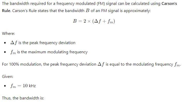
A frequency modulated wave is 100% modulated by 10 kHz modulating signal m(t). Then the bandwidth required is

Detailed Solution for Test: Electromagnetic & Analog Communications - 2 - Question 15


Test: Electromagnetic & Analog Communications - 2 - Question 16

A sinusoid x(t) = A cos2πfot is sampled at 5 times the Nyquist rate for 2.5 sec. A total of 250 samples are acquired value of fs and fm are given by

Detailed Solution for Test: Electromagnetic & Analog Communications - 2 - Question 16

Sampling frequency,

fs = 5 x (N quilt rate)

= 5 x f0= 10f0

No of samples =   = T x fs

⇒  250 = 2,5 x fs

Test: Electromagnetic & Analog Communications - 2 - Question 17

The angle-modulated signal with carrier frequency ωc = 27c x 106 is discribed by the equation

v(t) = 10 cos(ω​ct + 10sin200t + 20si n400πt) The deviation ratio is

Test: Electromagnetic & Analog Communications - 2 - Question 18

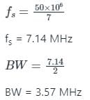
A PCM system uses a uniform quantizer followed by a 7-bit binary encoder. The bit rate of the system is equal to 50 x 106 bps.

Q. The maximum message bandwidth for which the system oeprates satisfactorily, is

Detailed Solution for Test: Electromagnetic & Analog Communications - 2 - Question 18

The bit rate is given by:

r = N × fs

where, r = Bit rate

N = No. of bit

fs = Sampling frequency

The maximum message signal bandwidth is given by:

Calculation:

Given, r = 50 × 106 bits/sec

N = 7


Test: Electromagnetic & Analog Communications - 2 - Question 19

The approximate output signal - to ­(quantization) noise ratio when a full - load sinusoidal modulating wave of frequency 1 MHz is applied to the input, is

Detailed Solution for Test: Electromagnetic & Analog Communications - 2 - Question 19

 Output signal to (quantization) noise ratio

where, 0 2n (where n = number of bits)

*Answer can only contain numeric values
Test: Electromagnetic & Analog Communications - 2 - Question 20

For an AM wave, the maximum voltage was found to be 10 V and the minimum voltage was found to be 5 V. The modulation index of the wave would be 


25 docs|263 tests
Information about Test: Electromagnetic & Analog Communications - 2 Page
In this test you can find the Exam questions for Test: Electromagnetic & Analog Communications - 2 solved & explained in the simplest way possible. Besides giving Questions and answers for Test: Electromagnetic & Analog Communications - 2, EduRev gives you an ample number of Online tests for practice

Top Courses for Electronics and Communication Engineering (ECE)

Download as PDF

Top Courses for Electronics and Communication Engineering (ECE)