Mechanical Engineering Exam  >  Mechanical Engineering Tests  >  Fluid Mechanics for Mechanical Engineering  >  Test: Fluid Dynamics Level - 2 - Mechanical Engineering MCQ

Test: Fluid Dynamics Level - 2 - Mechanical Engineering MCQ


Test Description

10 Questions MCQ Test Fluid Mechanics for Mechanical Engineering - Test: Fluid Dynamics Level - 2

Test: Fluid Dynamics Level - 2 for Mechanical Engineering 2025 is part of Fluid Mechanics for Mechanical Engineering preparation. The Test: Fluid Dynamics Level - 2 questions and answers have been prepared according to the Mechanical Engineering exam syllabus.The Test: Fluid Dynamics Level - 2 MCQs are made for Mechanical Engineering 2025 Exam. Find important definitions, questions, notes, meanings, examples, exercises, MCQs and online tests for Test: Fluid Dynamics Level - 2 below.
Solutions of Test: Fluid Dynamics Level - 2 questions in English are available as part of our Fluid Mechanics for Mechanical Engineering for Mechanical Engineering & Test: Fluid Dynamics Level - 2 solutions in Hindi for Fluid Mechanics for Mechanical Engineering course. Download more important topics, notes, lectures and mock test series for Mechanical Engineering Exam by signing up for free. Attempt Test: Fluid Dynamics Level - 2 | 10 questions in 25 minutes | Mock test for Mechanical Engineering preparation | Free important questions MCQ to study Fluid Mechanics for Mechanical Engineering for Mechanical Engineering Exam | Download free PDF with solutions
Test: Fluid Dynamics Level - 2 - Question 1

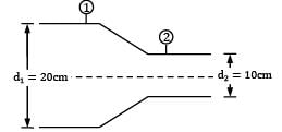
Consider steady, incompressible and irrotational flow through a reducer in a horizontal pipe, where the diameter is reduced from 20 cm to 10 cm. The absolute pressure in the 20 cm pipe just upstream of the reducer is 150 kPa absolute. The fluid has a vapour pressure of 50 kPa absolute and a

specific weight of 5 kN/m3. Neglecting frictional effects, the maximum discharge (in m3⁄sec) that can pass through the reducer without causing cavitation is


Detailed Solution for Test: Fluid Dynamics Level - 2 - Question 1

!s per Bernoulli’s equation

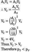
For flow along horizontal direction, an increase in flow velocity is accompanied by decrease in static pressure. Hence, applying continuity equation between section ① just upstream of the reducer and section ② downstream of reducer gives.

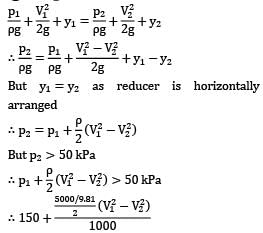
That is minimum pressure for flow along the reducer occurs at exit of reducer (section ②). This minimum pressure should be greater than vapor pressure else cavitation will occur in the system. ∴ p2 > 50 kPa !applying Bernoulli’s equation between section ① and ②

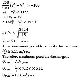
V1 < 5.11="" m="" />

Thus ,maximum possible velocity for section 1 is 5.11 m/sec.

Therefore maximum possible discharge is

Qmax = A1V1,max

Qmax = 0.16 m3/sec.

Test: Fluid Dynamics Level - 2 - Question 2

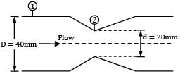
A venturi meter of 20 mm throat diameter is used to measure the velocity of water in a horizontal pipe of 40 mm diameter. If the pressure difference between the pipe and throat sections is found to be 30 kPa, and actual discharge is 2.4 Lt/sec. Predict coefficient of discharge for the venturimeter.


Detailed Solution for Test: Fluid Dynamics Level - 2 - Question 2

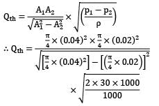
Let us consider theoretical discharge through the pipe, i.e. without considering any loss in the venturimeter.

If we apply Bernoulli’s equation and continuity equation between section ① in the pipe and section ②

∴ Qth = 2.513 × 10⁻³ m3/sec Qth = 2.513 Lt/sec Given, Qact = 2.4 Lt/sec Thus coefficient of discharge for the venturimeter is

Test: Fluid Dynamics Level - 2 - Question 3

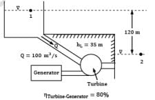
In a hydroelectric power plant, 100 m3 /s of water flows from an elevation of 120 m to a turbine, where electric power is generated (Fig). The total irreversible head loss in the piping system from point 1 to point 2 (excluding the turbine unit) is determined to be 35 m. Estimate the electric power output. (in MW)

Detailed Solution for Test: Fluid Dynamics Level - 2 - Question 3
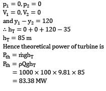
Considering steady state conditions, any fluid particle shall move along a streamline from 1 to 2, the streamline passing through the turbine. applying Bernoulli’s equation between 1 and 2

where hT is the head produced in the turbine and hf is the head loss.

As ① and ② lie on the free surfaces of head race and tail race respectively

Test: Fluid Dynamics Level - 2 - Question 4

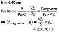
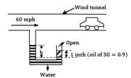
Air is drawn into a wind tunnel used for testing automobiles as shown in Fig. (ρair = 1.22 kg⁄m3 ; 1 mile = 1.6 km 1 inch = 2.54 cm)

(i) Determine the manometer reading h, when the velocity in the test section is 60 mph. Note that there is a 1-in. column of oil on the water in the manometer.

(ii) Determine the difference between the stagnation pressure on the front of the automobile and the pressure in the test section.
Detailed Solution for Test: Fluid Dynamics Level - 2 - Question 4
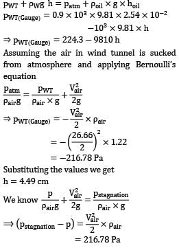
The manometer will read the pressure of the air in the wind tunnel because of its taping position. So equating pressure at the same level of water (in manometer)

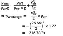
Assuming the air in wind tunnel is sucked from atmosphere and applying Bernoull’s equation

Substituting the value we get,

Test: Fluid Dynamics Level - 2 - Question 5

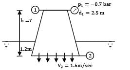
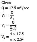
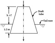
The rate of water through a vertical conical draft tube of a Kaplan turbine is 17.5 m3/s. The diameter of the draft tube on the side connected to the outlet of the turbine runner is 2.5 m and the average velocity at exit is 1.5 m⁄s. If the pressure at inlet to the tube is not to be less than the −0.7 bar, how far the tube should extend above the tail race. Neglect frictional effects and presume that exit of the draft tube lies 1.2 m below the tail water level.

Detailed Solution for Test: Fluid Dynamics Level - 2 - Question 5

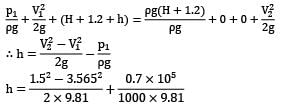
V1 = 3.565 m/sec

There is a possibility of mistake in the question, i.e. applying Bernoulli’s equation between section ① and ② and writing pressure at ② using hydrostatic law as ② lies 1.5 m below the free surface.

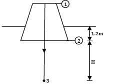
But please note that section ② represents flowing fluid, hence pressure cannot be predicted using hydrostatic law. Hence consider a point 3 far away from the tube along the centre streamline as shown.

Apply Bernoulli’s equation between ① and ③

Where hexit is the head loss at exit of draft tube.

Note: At exit of pipe into a reservoir, entire kinetic head is lost.

Also point 3 is the far away point where the fluid particle comes to rest.

∴ V3 = 0

And P3 can be predicted by hydrostatic law as fluid is at rest P3 = ρg(H + 1.2) Substituting these conditions in Bernoulli’s equation

h = 6.6 m

Test: Fluid Dynamics Level - 2 - Question 6

Gasoline flows through a constriction in a horizontal pipe where the diameter is reduced from 20 cm to 10 cm. The pressure in the 20 cm pipe just upstream of constriction is 60 kPa. Considering no loss of energy in the flow passage, make calculations for the maximum discharge (in L/s) that can be passed through the constriction without the occurrence of cavitation. The barometer reads 76 cm of mercury and for gasoline vapour pressure is 56 kPa (abs) and density is 650 kg/m3.


Detailed Solution for Test: Fluid Dynamics Level - 2 - Question 6

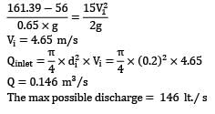
Since nothing is mentioned about the pressure at inlet. We assume it is measured by a pressure gauge, in terms of gauge. For cavitation to be avoided, the minimum pressure can’t go below 56 kPa (abs). Applying continuity at inlet and outlet

Pi = 60 × 103 + Patm

= 60 × 103 + 13.6 × 10³ × g × 0.76

= 161.39 kPa

P0 = 56 kPa

Substituting values

Test: Fluid Dynamics Level - 2 - Question 7

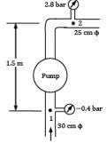
During the test of a centrifugal pump, water was drawn steadily from a reservoir through a vertical 30 cm diameter suction pipe, and the pump discharged the water into a horizontal 25 cm diameter delivery pipe. A Bourdon pressure gauge just outside the casing on the suction pipe read −0.4 bar gauge while the discharge pressure gauge indicated a pressure of 2.8 bar gauge. A vertical distance of 1.5 m intervened between the pipe centers at the sections where the gauges were attached. If the water discharge through the arrangement was measured as 0.1 m3⁄s, compute the power expended in running the pump.

Detailed Solution for Test: Fluid Dynamics Level - 2 - Question 7
Let H be the head that pump adds to the water, since the total head of outlet of pump>Total head at inlet

P2 = 2.8 × 10⁵

Z1 = 0 ; Z2 = 1.5 m

Applying continuity equation at inlet and outlet

solving the above for V1 and V2

Substituting values we get

32.61 + 0.031 + 1.5 = H = 34.14m/s

We know, power delivered by pump

=pQgH = 102 x 0.1 x 9.81 x 34.14

=33.49 kW

Assuming 100% pump efficiency

Power delivered = power consumed

= 33.5 kW

Test: Fluid Dynamics Level - 2 - Question 8

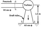
A 30 cm diameter pipe (called penstock) supplies water steadily to a turbine at 0.18 MN/m2. The water leaves the turbine on the exit side through a 60 cm pipe (called draft tube) with a pressure of −0.25 MN/m2. A vertical distance of 1.5 m separates the center of pipes at sections where measurements of pressure have been made. Calculate the power (in kW) delivered to the turbine from water if 0.25 m3 /s of water passes through the arrangement. Neglect frictional losses.

Detailed Solution for Test: Fluid Dynamics Level - 2 - Question 8

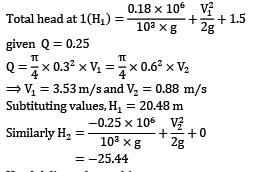
Head delivered to turbine = H1 − H2 = 20.48 + 25.4

= 45.92

Power delivered to turbine

= ρQg × Hdelivered

= 112.61 kW

Test: Fluid Dynamics Level - 2 - Question 9

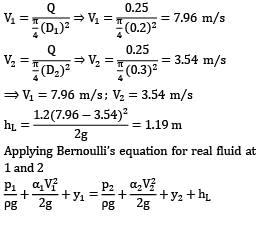
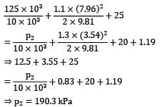
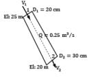
A pipe slopes downwards from 20 cm diameter at upstream section 1 (elevation 25 m) to 30 cm diameter at downstream section 2 (elevation 20 m). A pressure gauge installed at section 1 reads 125 kPa when the water flow rate is 0.25 m3⁄s. If the kinetic energy correction factor for sections 1 and 2 are 1.1 and 1.3 respectively, workout the reading of the pressure gauge at section 2. The loss of head through the pipe may be assumed as 1.2(V1 − V2)2/2g . For the pressure and temperature condition involved, specific weight of water equals 10 kN⁄m3
.


Detailed Solution for Test: Fluid Dynamics Level - 2 - Question 9

The pressure gauge at 2 will read 190.3 kPa

Test: Fluid Dynamics Level - 2 - Question 10

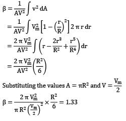
Find the momentum correction factor for the following velocity profile in a circular pipe

where v is the velocity at any radius r, Vm is the velocity at the pipe axis, and R is the radius of the pipe.


Detailed Solution for Test: Fluid Dynamics Level - 2 - Question 10
Momentum correction factor β,

Substituting the values A =

56 videos|104 docs|75 tests
Information about Test: Fluid Dynamics Level - 2 Page
In this test you can find the Exam questions for Test: Fluid Dynamics Level - 2 solved & explained in the simplest way possible. Besides giving Questions and answers for Test: Fluid Dynamics Level - 2, EduRev gives you an ample number of Online tests for practice
Download as PDF