Electrical Engineering (EE) Exam  >  Electrical Engineering (EE) Tests  >  GATE Electrical Engineering (EE) Mock Test Series 2025  >  Test: Frequency Response - Electrical Engineering (EE) MCQ

Test: Frequency Response - Electrical Engineering (EE) MCQ


Test Description

20 Questions MCQ Test GATE Electrical Engineering (EE) Mock Test Series 2025 - Test: Frequency Response

Test: Frequency Response for Electrical Engineering (EE) 2024 is part of GATE Electrical Engineering (EE) Mock Test Series 2025 preparation. The Test: Frequency Response questions and answers have been prepared according to the Electrical Engineering (EE) exam syllabus.The Test: Frequency Response MCQs are made for Electrical Engineering (EE) 2024 Exam. Find important definitions, questions, notes, meanings, examples, exercises, MCQs and online tests for Test: Frequency Response below.
Solutions of Test: Frequency Response questions in English are available as part of our GATE Electrical Engineering (EE) Mock Test Series 2025 for Electrical Engineering (EE) & Test: Frequency Response solutions in Hindi for GATE Electrical Engineering (EE) Mock Test Series 2025 course. Download more important topics, notes, lectures and mock test series for Electrical Engineering (EE) Exam by signing up for free. Attempt Test: Frequency Response | 20 questions in 60 minutes | Mock test for Electrical Engineering (EE) preparation | Free important questions MCQ to study GATE Electrical Engineering (EE) Mock Test Series 2025 for Electrical Engineering (EE) Exam | Download free PDF with solutions
Test: Frequency Response - Question 1

A parallel resonant circuit has a resistance of 2 kΩ and half power frequencies of 86 kHz and 90 kHz.1. The value of capacitor is

Detailed Solution for Test: Frequency Response - Question 1

BW = ω2 - ω1 = 2π(90 - 86)k = 8π krad/s
  
 = 19.89 nF

Test: Frequency Response - Question 2

A parallel resonant circuit has a resistance of 2 kΩ and half power frequencies of 86 kHz and 90 kHz.The value of inductor is

Detailed Solution for Test: Frequency Response - Question 2


 = 0.16 mH

1 Crore+ students have signed up on EduRev. Have you? Download the App
Test: Frequency Response - Question 3

A parallel resonant circuit has a resistance of 2 kΩ and half power frequencies of 86 kHz and 90 kHz.The quality factor is

Detailed Solution for Test: Frequency Response - Question 3

Test: Frequency Response - Question 4

A parallel resonant circuit has a midband admittance of 25 x 10-3 S, quality factor of 80 and a resonant frequency of 200 krad/s.The value of R is

Detailed Solution for Test: Frequency Response - Question 4

Ay mid-band frequency Z = R, Y = 1/R

Test: Frequency Response - Question 5

A parallel resonant circuit has a midband admittance of 25 x 10-3 S, quality factor of 80 and a resonant frequency of 200 krad/s.The value of C is

Detailed Solution for Test: Frequency Response - Question 5


 = 10 μF

Test: Frequency Response - Question 6

A parallel RLC circuit has R =1 kΩ and C = 1 μF. Thequality factor at resonance is 200. The value of inductor is

Detailed Solution for Test: Frequency Response - Question 6

 
⇒ L = 25 μH

Test: Frequency Response - Question 7

A parallel circuit has R =1 k , C = 50 μF and L = 10mH. The quality factor at resonance is

Detailed Solution for Test: Frequency Response - Question 7

Test: Frequency Response - Question 8

A series resonant circuit has an inductor L = 10 mH.The resonant frequency ωo = 106 rad/s and bandwidth is BW = 103 rad/s. The value of R and C will be

Detailed Solution for Test: Frequency Response - Question 8


 = 100pF

Test: Frequency Response - Question 9

A series resonant circuit has L = 1 mH and C = 10μF. The required R for the BW 15.9  Hz is

Detailed Solution for Test: Frequency Response - Question 9

⇒ 

Test: Frequency Response - Question 10

For the RLC parallel resonant circuit when R = 8 kΩ , L = 40 mH and C = 0.25 μF, the quality factor Q is

Detailed Solution for Test: Frequency Response - Question 10

Test: Frequency Response - Question 11

The maximum voltage across capacitor would be

Detailed Solution for Test: Frequency Response - Question 11

Thevenin equivalent seen by L - C combination


Open Circuit : v1 = 0, v∝ = 3V


Test: Frequency Response - Question 12

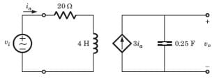
For the circuit shown in fig. resonant frequency fo is

Detailed Solution for Test: Frequency Response - Question 12

Applying 1 A at input port V1 = 10 V
voltage across 1 A source

Zin = Vtest
At resonance Im {Zin} = 0
⇒ 

Test: Frequency Response - Question 13

For the circuit shown in fig. the resonant frequency fo is 

Detailed Solution for Test: Frequency Response - Question 13


At resonance Im {Y} = 0


Test: Frequency Response - Question 14

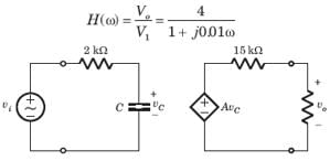
The network function of circuit shown in fig. is

Detailed Solution for Test: Frequency Response - Question 14


Test: Frequency Response - Question 15

Detailed Solution for Test: Frequency Response - Question 15

Test: Frequency Response - Question 16

Detailed Solution for Test: Frequency Response - Question 16

Test: Frequency Response - Question 17

The value of input frequency is required to cause again equal to 1.5. The value is

Detailed Solution for Test: Frequency Response - Question 17

For any value of ω, R,C gain ≤ 1.
Thus (D) is correct option.

Test: Frequency Response - Question 18

In the circuit of fig. phase shift equal to -450 is required at frequency ω =20 rad/s . The value of R is

Detailed Solution for Test: Frequency Response - Question 18


phase shift = - tan-1 ωCR = -450°
ωCR = 1,

20 x 1 x 10-6 R = 1 ⇒ R = 50KΩ

Test: Frequency Response - Question 19

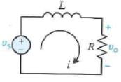
For the circuit of fig., Vs is the source voltage and the response is the resistance voltage Vo, R = 30Ω and L = 2H. Suppose the input frequency is adjusted until the gain is equal to 0.6. The value of the frequency is
Detailed Solution for Test: Frequency Response - Question 19


Test: Frequency Response - Question 20

Bode diagram of the network function Vo /Vfor the circuit of fig.  is

Detailed Solution for Test: Frequency Response - Question 20


-20 dB/decade line starting from ω = 5.56 rad/s
20 dB/decade line starting from ω = 16.67 rad/s
Hence -20 dB/decade line for 5.56 < ω < 16.67 parallel to ω axis to ω >16.67 

25 docs|247 tests
Information about Test: Frequency Response Page
In this test you can find the Exam questions for Test: Frequency Response solved & explained in the simplest way possible. Besides giving Questions and answers for Test: Frequency Response, EduRev gives you an ample number of Online tests for practice

Top Courses for Electrical Engineering (EE)

Download as PDF

Top Courses for Electrical Engineering (EE)