Civil Engineering (CE) Exam  >  Civil Engineering (CE) Tests  >   Test: Hydraulic Machines Level - 2 - Civil Engineering (CE) MCQ

Test: Hydraulic Machines Level - 2 - Civil Engineering (CE) MCQ


Test Description

20 Questions MCQ Test - Test: Hydraulic Machines Level - 2

Test: Hydraulic Machines Level - 2 for Civil Engineering (CE) 2025 is part of Civil Engineering (CE) preparation. The Test: Hydraulic Machines Level - 2 questions and answers have been prepared according to the Civil Engineering (CE) exam syllabus.The Test: Hydraulic Machines Level - 2 MCQs are made for Civil Engineering (CE) 2025 Exam. Find important definitions, questions, notes, meanings, examples, exercises, MCQs and online tests for Test: Hydraulic Machines Level - 2 below.
Solutions of Test: Hydraulic Machines Level - 2 questions in English are available as part of our course for Civil Engineering (CE) & Test: Hydraulic Machines Level - 2 solutions in Hindi for Civil Engineering (CE) course. Download more important topics, notes, lectures and mock test series for Civil Engineering (CE) Exam by signing up for free. Attempt Test: Hydraulic Machines Level - 2 | 20 questions in 40 minutes | Mock test for Civil Engineering (CE) preparation | Free important questions MCQ to study for Civil Engineering (CE) Exam | Download free PDF with solutions
Test: Hydraulic Machines Level - 2 - Question 1

A radial flow hydraulic turbine is required to be designed to produce 20 MW under a head of 16 m at a speed of 90 rpm. A geometrically similar model with an output of 30 kW and a head of 4 m is to be tested under dynamically similar conditions. What is the required impeller diameter ratio between the model and prototype?


Detailed Solution for Test: Hydraulic Machines Level - 2 - Question 1
Equating the power coefficients (π term containing the power P) for the model and prototype, we can write

(where subscript 1 refers to the prototype and subscript 2 to the model) Considering the fluids to be incompressible, and same for both the prototype and model, we have

Equating the head coefficients (π term containing the head H)

Then,

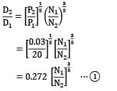
Therefore equating the diameter ratios from equation 1 and 2 we have

= 1.84

Hence, N2 = N1(1.84)5/2 = 90 × (1.84)5/2

= 413.32 rpm

From equation ①

Test: Hydraulic Machines Level - 2 - Question 2

Which one of the following statements is correct with respect to axial flow 50% reaction turbine?

Detailed Solution for Test: Hydraulic Machines Level - 2 - Question 2
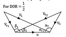
For axial flow (u1 = u2 = u)

β1 = α2

β2 = α1

|V1| = |Vr2 |

|Vr1 | = |V2|

Velocity triangles are symmetrical.

Test: Hydraulic Machines Level - 2 - Question 3

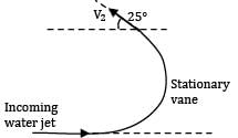
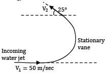
A water jet impinges tangentially at one tip of a stationary vane having an inlet angle of zero degree and an outlet angle 25 degree. The incoming velocity of jet is 50 meters per second. Determine the component of force acting on the vane in the direction of jet velocity. Assume water flow equivalent to 1 kg/s.

Detailed Solution for Test: Hydraulic Machines Level - 2 - Question 3

Given V1 = 50 m ⁄ s

We get V1 = V2 = 50 m/s

So force acting along the direction of jet

= ρQ(V1 + V2 cos 25)

= 95.31 N

Test: Hydraulic Machines Level - 2 - Question 4

Which of the following statements are correct?

1. The specific speed of a turbine is the speed at which a geometrically similar turbine develops unit power under the unit head at its maximum efficiency.

2. The specific speed is dimensionless parameter used for the selection of turbines.

3. The function of guide vanes in reaction turbines is to minimize shock at entry of the fluid onto the runner blades.

Select the correct answer using the code given below.

Detailed Solution for Test: Hydraulic Machines Level - 2 - Question 4
Specific speed is not dimensionless, although it doesn’t have the dimension of speed either.

Test: Hydraulic Machines Level - 2 - Question 5

A centrifugal pump lifts 0.0125 m3⁄s of water from a well with a static lift of 30 m. If the brake power of the driving electric motor is 5 kW, what is the overall efficiency of the pump-set?

Detailed Solution for Test: Hydraulic Machines Level - 2 - Question 5
Power supplied by the pump (Poutput ) = ρQgH

Power supplied to the pump (Pinput) = 5 kW

=0.735 = 73.5%

Test: Hydraulic Machines Level - 2 - Question 6

Mainly hydraulic turbines are used to drive the electrical alternators which require maintaining the peripheral speed constant even at part load conditions to avoid the change in frequency of electric power. The governing of the hydraulic turbine is done by

Detailed Solution for Test: Hydraulic Machines Level - 2 - Question 6
As the turbines are required to run at a constant speed (because they are attached to electrical alternators) the speed of the water can’t be altered and hence the head developed by the turbine stays the same. Then the only other factor that can be changed is the discharge of water to control the power, and to do that the area of the flow needs to be controlled. Flywheel is only used to store energy, not governing.

Test: Hydraulic Machines Level - 2 - Question 7

The hydraulic efficiency of a turbine is the ratio of

Detailed Solution for Test: Hydraulic Machines Level - 2 - Question 7
Hydraulic efficiency = energy output of the rotor/energy supplied to the turbine.

Test: Hydraulic Machines Level - 2 - Question 8

In axial flow pumps and compressors the combined velocity diagram with common base is used to determine change in

Detailed Solution for Test: Hydraulic Machines Level - 2 - Question 8
For axial flow compressors/pumps, U1 = U2 , which is represented as the common base for the combined velocity triangles. Now although V2 − V1 and Vr2 − Vr1 can be calculated from the velocity triangles, but the most important parameter that the velocity triangles are used for is Vw2 − Vw1 (difference of whirl velocities at outlet and inlet) which helps to calculate the head given to the fluid by the pump/compressor.

Test: Hydraulic Machines Level - 2 - Question 9

Consider the following statements. 1. The distinguishing features of radial flow reaction turbines are: (i) Only a part of the total head of water is converted into velocity head before it reaches the runner. (ii) The flow-through water completely fills all the passages in the runner. 2. Kaplan turbine is essentially a propeller working in reverse, and its blades are so mounted that all the blade angles can be adjusted simultaneously by means of suitable gearing even as the machine is in operation. 3. A draft tube is a pipe of gradually increasing cross-sectional area which must be airtight, and under all conditions of operation, its lower end must be submerged below the level of the discharged water in the tailrace.

Which of the above statements are correct?

Detailed Solution for Test: Hydraulic Machines Level - 2 - Question 9
Inside reaction turbines, the pressure everywhere is different than atmospheric, so air can’t be present inside the turbine or the draft tube. Reaction turbines can use both kinetic and pressure head to produce energy and Kaplan turbine is a type of propeller turbine so all the 3 statements are correct.

Test: Hydraulic Machines Level - 2 - Question 10

The mean bucket speed of a Pelton turbine is 15 m/s. The rate of flow of water supplied by the jet under a head of 42 m is 1 m3 /s. If the jet is deflected by the buckets at an angle of 165°, find the power of the turbine. (in kW). (Take coefficient of velocity (Cv = 0.985).


Detailed Solution for Test: Hydraulic Machines Level - 2 - Question 10
Bucket speed is the same at both inlet and outlet of the water jet.

Therefore, U1 = U2 = 15 m/s Velocity of jet at inlet V1 = 0.985(2 × 9.81 × 42)1/2

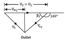
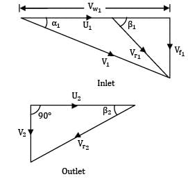
= 28.27 m/s Now the inlet and outlet velocity triangles are drawn as shown below.

From inlet velocity triangle,

Vr1 = V1 − U1 = 28.27 − 15 = 13.27 m/s

Vw1 = V1 = 28.27 m/s

The blade outlet angle is given by

β2 = 180° − 165° = 15°

Neglecting the frictional losses in the bucket

Vr1 = Vr2 = 13.27 m/s

From outlet velocity triangle

= U2 − Vr2 cos β2 [here U2 > Vr2 cos β2]

= 15 − 13.27 cos 15°

= 2.18 m/s

Power developed

P = ρQ(Vw1 − Vw2)U1

= 103 × 1 × (28.27 − 2.18) × 15

= 391.35 kW

Test: Hydraulic Machines Level - 2 - Question 11

Consider the following advantages of rotary pumps compared to reciprocating pumps:

1. Steady discharge which increases with decrease in head

2. Suitable for handling fluids with suspended solid particles

3. Less bulky than positive displacement pumps 4. Can be started with open delivery with least load

Which of the above advantages are correct?

Detailed Solution for Test: Hydraulic Machines Level - 2 - Question 11
Rotary pumps deliver almost steady flow because of absence of any reciprocating motion, since there is no piston-cylinder arrangement with a clearance between them that can fail if any particles gets stuck in the clearance, hence rotary pumps can handle fluids with suspended solid particles, and since rotary pumps have low pressure ratio, they are constructed with thinner walls and light in weight.

Test: Hydraulic Machines Level - 2 - Question 12

Statement I: The speed of a governed water turbine will remain constant irrespective of load.

Statement II: In governing, the water supply is regulated to maintain the speed constant.

Detailed Solution for Test: Hydraulic Machines Level - 2 - Question 12
As the turbines are connected with generators, so the turbines must run with a constant speed so that the frequency of the electric current produced by the generators stay the same. To do that the discharge to the turbine needs to be altered suitably to keep the speed constant.

Test: Hydraulic Machines Level - 2 - Question 13

A single jet Pelton turbine is required to drive a generator to develop 10 MW. The available head at the nozzle is 762 m. Assuming electric generator efficiency 95%, Pelton wheel efficiency 87%, coefficient of velocity for nozzle 0.97, mean bucket velocity 0.46 of jet velocity, outlet angle of the buckets 15° and the friction of the bucket reduces the relative velocity by 15%, find the diameter of the jet (in mm), if the ratio of mean bucket circle diameter to the jet diameter is not to be less than 10.


Detailed Solution for Test: Hydraulic Machines Level - 2 - Question 13
Mechanical power output of the turbine

= Electrical power output / Generator efficiency

= 10 / 0.95 = 10.53 MW

Pelton wheel efficiency

Where Q is the flow rate through the turbine.

Then, Q = = = 1.62m3

If d1 is the diameter of the jet, we can write

Where Cv is the coefficient of velocity, then

Which given d1 = 0.132m = 132 mm

Test: Hydraulic Machines Level - 2 - Question 14

In a hydroelectric scheme a number of Pelton wheels are to be used under the following conditions: Total output required 30 MW; gross head 245 m; speed 6.25 rev/s; 2 jets per wheel; Cv of nozzles 0.97; maximum overall efficiency (based on conditions immediately before the nozzles) 81.5%; dimensionless specific speed not to exceed 0.022 rev. per jet; head lost to friction in pipeline is 12 m. Ratio of blade to jet speed is 0.46.

Calculate the number of wheels required.

Detailed Solution for Test: Hydraulic Machines Level - 2 - Question 14
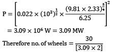
Dimensionless specific speed for turbine

Here KsT = 0.022 rev. per jet

The available head to the turbine (i.e., at the inlet to the nozzle)

H = 245 − 12 = 233 m

Hence, power per jet

=3.09 x 10⁶W = 3.09 MW

Therefore no. of wheels =

= 5 (No. of wheels would be an integer)

Test: Hydraulic Machines Level - 2 - Question 15

Consider the following statements with regard to hydraulic turbines:

1. Kaplan turbines are most efficient at part load operations.

2. If n is the number of jets in a Pelton turbine, then the specific speed is proportional to n2.

3. The flow ratio of Francis turbines are in the range of 0.1-0.3.

Which of the above statements is/are correct?

Detailed Solution for Test: Hydraulic Machines Level - 2 - Question 15
Kaplan turbines are the most efficient turbines under part load conditions. If n is the number of jets in the Pelton turbine, then Q α n and hence power α n. since specific speed is α √ power. So, specific speed α √n. Therefore statement (II) is wrong. The flow ratio is defined as the ratio of velocity of flow at inlet to theoretical jet velocity and it is in the ratio of 0.1-0.3 for the Francis turbine.

Test: Hydraulic Machines Level - 2 - Question 16

A Francis turbine has a diameter of 1.4 m and rotates at 430 rpm. Water enters the runner without shock with a flow velocity of 9.5 m/s and leaves the runner without whirl with an absolute velocity of 7 m/s. The difference between the sum of the static and potential heads at entrance to the runner and at the exit from the runner is 62 m. The turbine develops 12.25 MW. The flow rate through the turbine is 12 m3/s for a net head of 115 m.

Find the absolute velocity of water at entry to the runner and the angle of the inlet guide vanes.

Detailed Solution for Test: Hydraulic Machines Level - 2 - Question 16
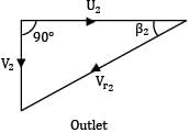
The inlet and outlet velocity triangles are drawn as shown below.

Runner tip speed

Since Vw2 = 0,

Power given to the runner by water = pQVw1U1

Hence, 12.25 x 106 = 103 x 12 x Vw1 x 31.52

Which guides vane angle 1 is given by

From the inlet velocity diagram, the absolute velocity at runner inlet

= 33.75 m/s

Test: Hydraulic Machines Level - 2 - Question 17

Calculate the net positive suction head (NPSH) of a centrifugal pump using the following data. Vapour pressure of the liquid = 26.66 kN/m2 .

Distance between the level of liquid in the reservoir and suction line = 12. m.

Density of the liquid = 865 kg/m3 Friction in the suction line = 3.5 J/kg Reservoir is open to the atmosphere.


Detailed Solution for Test: Hydraulic Machines Level - 2 - Question 17
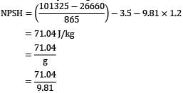
NPSH in terms of J/kg, i.e., in energy units is given by the following equation.NPSH in terms of J/kg, i.e., in energy units is given by the following equation.

pa = pressure over the liquid surface = 101325 N/m2 Substituting the values of various parameters in the above equation gives

= 7.24 m

Test: Hydraulic Machines Level - 2 - Question 18

Statement I: Cavitation occurs at the entrance of the turbine while it occurs at the exit of the pump.

Statement II: In both the cases local pressure at these points falls below the vapour pressure of the flowing liquid.

Detailed Solution for Test: Hydraulic Machines Level - 2 - Question 18
Cavitation occurs at the exit of the turbine and inlet of the pump because the pressure at these regions can fall below the vapour pressure of the liquid. So the statement (I) is wrong.

Test: Hydraulic Machines Level - 2 - Question 19

Two geometrically similar pumps are running at 1000 rpm speed (both). If one pump has impeller diameter of 0.3 m and discharges 20 lt/sec against 20 m head, and the other pump gives half of this discharge rate; calculate the head and diameter of second pump.

Detailed Solution for Test: Hydraulic Machines Level - 2 - Question 19

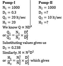
We know Q ? ND3

Substituting values gives us

D2 = 0.238

Similarly, H ? N2D2

H2 = 12.58

Test: Hydraulic Machines Level - 2 - Question 20

A centrifugal pump is fully primed, but on starting it fails to deliver fluid. The probable reasons are listed below:

1. Leaky foot valve or suction line

2. Suction head is very low

3. Insufficient motor speed

4. Damaged or closed delivery valve

Which of these reasons are correct?

Detailed Solution for Test: Hydraulic Machines Level - 2 - Question 20
If the delivery valve is closed, then there will be no discharge. If the motor speed is insufficient, it may happen that the head provided to the fluid is too low to overcome the frictional losses in the delivery pipe and hence no discharge will occur. If the suction head is too low, it may happen that the energy given to the pump is not enough to lift the water up. But a leaky foot valve or suction line will not prevent discharge since the leak can’t cause 100% loss of water mass.
Information about Test: Hydraulic Machines Level - 2 Page
In this test you can find the Exam questions for Test: Hydraulic Machines Level - 2 solved & explained in the simplest way possible. Besides giving Questions and answers for Test: Hydraulic Machines Level - 2, EduRev gives you an ample number of Online tests for practice
Download as PDF