Test: Hydraulic Machines Level - 3 - Civil Engineering (CE) MCQ
20 Questions MCQ Test - Test: Hydraulic Machines Level - 3
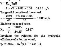
A Pelton wheel having semi-circular buckets functions under a head of 150 m and consumes 50 liters of water per second. If 60 cm diameter wheel turns 600 revolutions per minute, make calculations for the hydraulic efficiency of the wheel. Presume coefficient of velocity KV = unity.
(A) 90
(B) 91
A Pelton wheel works at the foot of a dam because of which the head available at the nozzle is 220 m. The nozzle diameter is 20 cm and the coefficient of velocity is 0.98. The wheel operates at 250 rev/min and develops 3.75 MW of power. Assuming that the blade outlet angle is 16° and the jet speed ratio is 0.46, make calculations for the wheel diameter at the pitch circle of the blades, and the turbine efficiency.
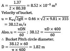
A Pelton wheel is required to develop 4000 kW at 400 revs/min, operating under an available head of 350 m. There are two equal jets and the bucket deflection angle is 165°. Calculate the bucket pitch circle diameter, the cross-sectional areas of each jet. Make the following assumptions: (i) Overall efficiency is 85% when the water is discharged from the wheel in a direction parallel to the axis of rotation. (ii) Coefficient of velocity of the nozzle Kv = 0.97 and the blade speed ratio Ku = 0.46. (iii) Relative velocity of water at exit from the bucket is 0.86 times the relative velocity at inlet.
At a particular hydroelectric power plant, water available under a head of 250 m is delivered to the power house through three pipes each 2500 m long. Through these pipes, friction loss is estimated to be 20 m.
The project is required to produce a total shaft output of 13.25 MW by installing a number of single jet Pelton wheels whose specific speed is not to exceed 38.5. The other pertinent data is Wheel speed = 650 revolutions per minute Ratio of bucket to jet speed = 0.46 Overall efficiency of the wheel = 85% For nozzle Cd = 0.94 and Kv = 0.97.
Pipe friction coefficient f = 0.005 in the
Formula hf = ![]()
Determine: (i) jet diameter (ii) Diameter of supply pipes
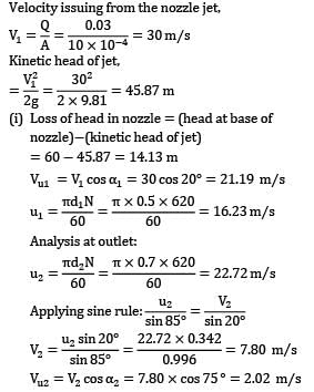
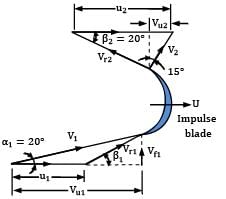
An outward radial flow impulse turbine has nozzles with a total area of 10 cm2 . The guide vanes make an angle of 20° to the wheel tangent at exit. The inner and outer diameters are 0.5 m and 0.7 m respectively. The moving vanes have an outlet angle of 20° to the wheel tangent. The turbine develops 11.75 kW at the shaft running at 620 rpm under a head of 60 m, at a discharge of 0.03 m3⁄s. The water at discharge end leaves the runner in a forward direction and is inclined at 15° to the radius. Calculate
(i) the head lost in the nozzle
(ii) the head lost by the bearing friction
An inward flow reaction turbine works under a total head of 28 m. The velocity of wheel periphery at inlet is 15 m/s. The outlet pipe of the turbine is 30 cm in diameter and the turbine is supplied with 250 liters of water per second. The radial velocity of flow through the wheel is the same as velocity in outlet pipe. Neglecting friction, determine
a. vane angle at inlet
b. guide vane angle

Two inward flow turbine runners have the same diameter 0.75 m and work under the same head with a velocity of flow of 6 m/s.
One runner operates at 450 rpm and has an inlet blade angle of 60-degree. Determine the speed (in rpm) at which the other turbine should run if its inlet blade angle is 105-degree. Assume that both the turbines have the same efficiency and radial discharge at outlet.
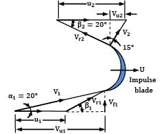
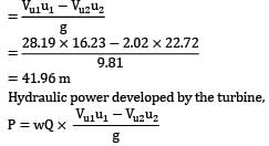
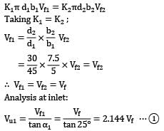
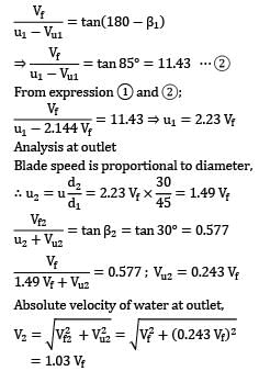
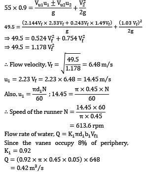
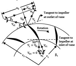
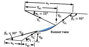
The runner of an inward flow reaction turbine is of 45 cm diameter and 5 cm width at the outer periphery; the corresponding dimensions at the inner periphery are 30 cm and 7.5 cm respectively, and vanes occupy 8% of the periphery. The guide vane angle is 25° to the tangent to the runner and the moving vanes have an inlet angle of 95° (vanes inclined forward to the direction of motion) and an exit angle of 30°. Hydraulic and mechanical friction losses respectively amount to 10% and 5% of the supply head, and the pressure in the outer casing is 55 cm more than that at discharge from the runner. You are required to work out the speed of the runner for no shocks at entry and the power available at the turbine shaft.
Refer to Fig. for nomenclature and the vector diagrams.
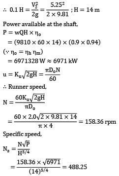
For a Kaplan turbine with runner diameter 4 m, the discharge is 60 m3⁄s and the hydraulic and mechanical efficiencies are stated to be 90 percent and 94 percent respectively. The diameter of the boss is 0.3 times the runner diameter and the speed ratio is 2.0. Assuming that discharge is free and there is no swirl at outlet, calculate the specific speed.
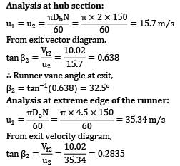
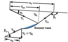
A propeller turbine has been designed to develop 22000 kW under a head of 20 m whilst turning 150 revolutions per minute. The relevant data is: hydraulic efficiency 95%; overall efficiency 88%; outer diameter 4.5 m and diameter of the hub 2 m. Determine the runner exit vane angles at the hub and at the outer periphery. Assume that the turbine discharges without whirl at exit.
Refer Fig. for nomenclature and velocity vector diagrams.
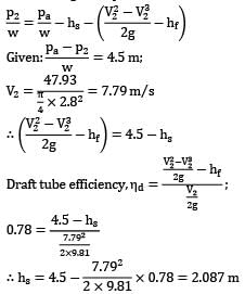
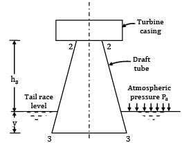
A Kaplan turbine develops 2250 kW under a net head of 5.5 m and with overall efficiency 87 percent. The draft tube has a diameter of 2.8 m at its inlet and has an efficiency of 78 percent. In order to avoid cavitation, the pressure head at entry to the draft tube must not drop more than 4.5 m below atmosphere. Calculate the maximum height at which the runner may be set above the tail race level.
A turbine is to operate under a head of 25 meters at 200 rpm. The discharge is 9 m3/s. If the turbine efficiency is 90% determine: (i) specific speed of the turbine (ii) power developed under a head of 20 meters
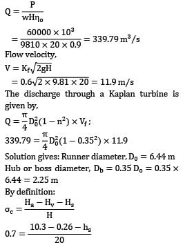
A hydro-electric power station required to generate 60,000 kW at 50 cycle frequency and at the available head of 20 m suggests the use of Kaplan turbine for which specific speed is 600 units. Make calculations for:
(i) hub diameter of the turbine assuming flow ratio 0.6 and that hub diameter of the wheel is 0.35 times the outside diameter
(ii) maximum safe elevation of runner to avoid cavitation taking vapour pressure 0.26 m of water and critical value of Thomas’s cavitation factor 0.7
A water turbine is stated to have 50 percent degree of reaction. What is the physical meaning of this statement? Classify the Pelton, Francis and Kaplan runners according to the ranges of degree of reaction. Does the specific speed increase or decrease with an increase in the degree of reaction of a hydraulic turbine?
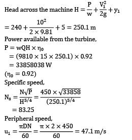
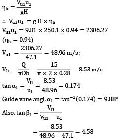
The velocity and pressure head at the entrance to the volute casing of a Francis turbine are 10 m/s and 240 m, and the elevation above tail race is 5 m. The shaft is vertical and the machine discharges 15 m3⁄s when turning 450 revolutions per minute. The mean diameter for the runner blades is 2 m and the width at inlet is 28 cm. If the discharge is to be axial, calculate:
(i) the specific speed
(ii) the degree of reaction
Assume values for the hydraulic and overall efficiencies are 94% and 92% respectively.
Why pumps are generally less efficient than turbines?
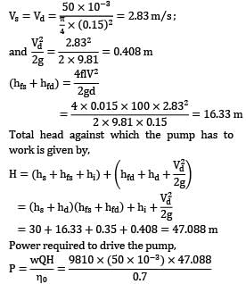
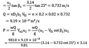
A centrifugal pump is required to deliver 50 litres of water per second to a height of 30 m through a 100 m long pipe of 15 cm diameter. The inlet losses in the suction pipe are estimated to be 0.35 m. Assuming an overall efficiency of 70 percent and taking Darcy’s friction coefficient 0.015 for the pipeline, determine the power required to drive the pump, in kW.
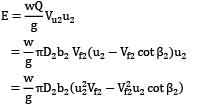
A centrifugal pump with impeller diameter 20 cm at outlet and width of outlet passage 2 cm has swept back blades at 25° to the tangent to the periphery. Calculate the power (in Watt) requirement while operating at 300 rpm under the condition of maximum efficiency.
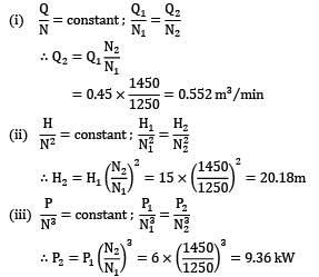
A single stage centrifugal pump discharge 0.45 m3 of water per minute producing a head of 15 m. A motor drives the pump and the tachometer registers a speed of 1250 rpm. At this speed the brake power necessary to drive the pump is 6 kW. If the number of revolutions is increased to 1450 rpm, find the new discharge, head and brake power.
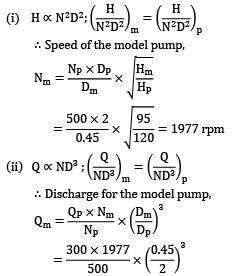
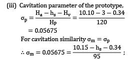
A single stage centrifugal pump runs at 500 rpm and delivers 300 m3⁄min of water against a head of 120 m. The pump impeller is 2 m in diameter and it has a positive suction lift (including the velocity head and friction) of 3 m. Laboratory tests are to be conducted on a model with 45 cm impeller and on a reduced head of 95 m. Calculate the speed, discharge and suction lift for the laboratory tests. Assume vapour head Hv = 0.34 m of water and atmospheric head Ha = 10.15 m of water.
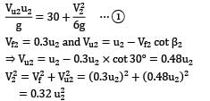
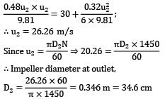
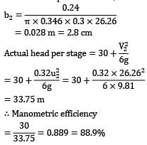
A 4-stage centrifugal pump supplying water is to be designed for a total lift of 120 m when running at 1450 rpm; its discharge under these conditions is 0.24 m3 /s. The vanes are set back at an angle of 30° with the tangent to the wheel at outlet, and the impeller is surrounded by guide vanes. The water enters the vane passages in a radial direction, the velocity of flow through the impeller is 0.3 of the outlet peripheral velocity and the losses in the pump amount to one-third of the velocity head at discharge from the impeller. Find the width of the impeller at outlet, and the manometric efficiency.
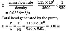
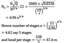
A multistage boiler feed pump is required to pump 115 × 103 kg of water per hour against a pressure difference of 3150 kN/m2 when running at a speed of 3000 rev/min. The density of preheated feed water is 950 kg/m3. If all the impellers are identical and the specific speed per stage is not to be less than 22, work out a. the diameter of the impeller b. the shaft power required to drive the pump.
It may be presumed that overall efficiency is 77% and peripheral velocity of the impeller is given by u = 0.96√2gh where h is the head per stage.


