Civil Engineering (CE) Exam  >  Civil Engineering (CE) Tests  >  GATE Civil Engineering (CE) 2025 Mock Test Series  >  Test: ILD & Rolling Loads -2 - Civil Engineering (CE) MCQ

Test: ILD & Rolling Loads -2 - Civil Engineering (CE) MCQ


Test Description

10 Questions MCQ Test GATE Civil Engineering (CE) 2025 Mock Test Series - Test: ILD & Rolling Loads -2

Test: ILD & Rolling Loads -2 for Civil Engineering (CE) 2025 is part of GATE Civil Engineering (CE) 2025 Mock Test Series preparation. The Test: ILD & Rolling Loads -2 questions and answers have been prepared according to the Civil Engineering (CE) exam syllabus.The Test: ILD & Rolling Loads -2 MCQs are made for Civil Engineering (CE) 2025 Exam. Find important definitions, questions, notes, meanings, examples, exercises, MCQs and online tests for Test: ILD & Rolling Loads -2 below.
Solutions of Test: ILD & Rolling Loads -2 questions in English are available as part of our GATE Civil Engineering (CE) 2025 Mock Test Series for Civil Engineering (CE) & Test: ILD & Rolling Loads -2 solutions in Hindi for GATE Civil Engineering (CE) 2025 Mock Test Series course. Download more important topics, notes, lectures and mock test series for Civil Engineering (CE) Exam by signing up for free. Attempt Test: ILD & Rolling Loads -2 | 10 questions in 30 minutes | Mock test for Civil Engineering (CE) preparation | Free important questions MCQ to study GATE Civil Engineering (CE) 2025 Mock Test Series for Civil Engineering (CE) Exam | Download free PDF with solutions
Test: ILD & Rolling Loads -2 - Question 1

Consider the beam ABCD and the influence line as shown below. The influence line pertains to
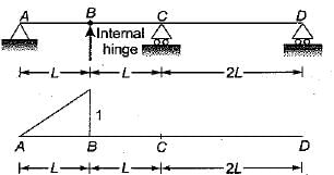
Test: ILD & Rolling Loads -2 - Question 2

Shape of influence line diagram for bending moment at D in a symmetrical two hinged arch given above is

Test: ILD & Rolling Loads -2 - Question 3

The absolute maximum Bending Moment in a simply supported beam of span 20 m due to a moving UDL of 4 t/m spanning over 5 m is
Detailed Solution for Test: ILD & Rolling Loads -2 - Question 3

Absolute maximum bending moment will occur at the centre when the load is spread equally on either side of the centre.

Test: ILD & Rolling Loads -2 - Question 4


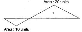
​Influence line diagram for a truss member is shown in the above figure. Positive values indicate tension. Dead load of the truss is 20 kN/m and the live load is 10 kN/m. Live load is longer than the span. Maximum tensile force in the member is:

Detailed Solution for Test: ILD & Rolling Loads -2 - Question 4

Tensile force due to D.L.
= (20 - 10) x 20 = 200 kN
Maximum Tensile force due to L.L.
=  20 x 10 = 200 kN
Thus maximum tensile force
= 200 + 200 = 400 kN

Test: ILD & Rolling Loads -2 - Question 5

The influence line for horizontal thrust of a two- hinged parabolic arch of span i’ and rise 'h' will be shown in

Detailed Solution for Test: ILD & Rolling Loads -2 - Question 5

Figure in (a) is the I.L.D. of horizontal, thrust for three hinged arch

Test: ILD & Rolling Loads -2 - Question 6

A Warren truss is supported as shown in the given figure. Which one of the following diagrams represents the influence line for the force in member U3U4?

Detailed Solution for Test: ILD & Rolling Loads -2 - Question 6

Introduce a cut through U3U4, U3L4and L3L4. The member forces of L3L4 and U3L4 pass through support at L4 . So w hen load is at L0, L1 L2, L3 and L4. the total moment of all the force except force in U3U4 on the right part of cut section is zero. So from moment equilibrium the force in U3U4 will remain zero when load is between. L0 and L4.
When load is at L5, the force in member U3U4

Test: ILD & Rolling Loads -2 - Question 7

A simply-supported beam with overhangs is shown in the figure. The influence line diagram for shear in respect of a section just to the right of the support 'A wiil be as shown in 

Test: ILD & Rolling Loads -2 - Question 8

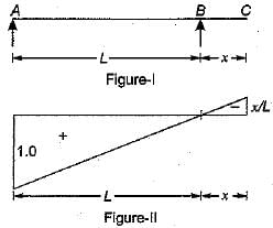
A simply supported beam is shown in the figure-I. The influence line for the beam is drawn in figure-II, Which one of the following statements is correctly associated with the figure-II?
Detailed Solution for Test: ILD & Rolling Loads -2 - Question 8

Since the unit value of I.L.D. is 1,0 at A. So this is for reaction at support A

Test: ILD & Rolling Loads -2 - Question 9

Consider the following statements:
1. An influence line for a function (example: moment shear force, reaction, deflection) in a structure is a curve which shows its variation at a particular section of the structure for various positions of a moving unit load.
2. The influence line for bending moment/shear force must not be confused with bending moment diagram and shear force diagram for the structure.
3. The bending moment diagram and shear force diagram shows the moment/shear values at all sections of the structure. The influence line diagram for BM/SF is always drawn for a moving unit point load and for a particular section only

Of these statements:

Test: ILD & Rolling Loads -2 - Question 10

Which one of the following equations represents influence line of fixed end moment at B of the fixed beam AB of length l with origin at A?

Detailed Solution for Test: ILD & Rolling Loads -2 - Question 10

For the influence line of fixed end moment at B, release the moment at B and give unit rotation, the deformed shape will represent the influence line.

due to unit load at x distance from A.

31 docs|280 tests
Information about Test: ILD & Rolling Loads -2 Page
In this test you can find the Exam questions for Test: ILD & Rolling Loads -2 solved & explained in the simplest way possible. Besides giving Questions and answers for Test: ILD & Rolling Loads -2, EduRev gives you an ample number of Online tests for practice
Download as PDF