Electrical Engineering (EE) Exam  >  Electrical Engineering (EE) Tests  >  GATE Electrical Engineering (EE) Mock Test Series 2026  >  Test: Logic Gates & Switching Circuits- 1 - Electrical Engineering (EE) MCQ

Test: Logic Gates & Switching Circuits- 1 - Electrical Engineering (EE) MCQ


Test Description

10 Questions MCQ Test GATE Electrical Engineering (EE) Mock Test Series 2026 - Test: Logic Gates & Switching Circuits- 1

Test: Logic Gates & Switching Circuits- 1 for Electrical Engineering (EE) 2025 is part of GATE Electrical Engineering (EE) Mock Test Series 2026 preparation. The Test: Logic Gates & Switching Circuits- 1 questions and answers have been prepared according to the Electrical Engineering (EE) exam syllabus.The Test: Logic Gates & Switching Circuits- 1 MCQs are made for Electrical Engineering (EE) 2025 Exam. Find important definitions, questions, notes, meanings, examples, exercises, MCQs and online tests for Test: Logic Gates & Switching Circuits- 1 below.
Solutions of Test: Logic Gates & Switching Circuits- 1 questions in English are available as part of our GATE Electrical Engineering (EE) Mock Test Series 2026 for Electrical Engineering (EE) & Test: Logic Gates & Switching Circuits- 1 solutions in Hindi for GATE Electrical Engineering (EE) Mock Test Series 2026 course. Download more important topics, notes, lectures and mock test series for Electrical Engineering (EE) Exam by signing up for free. Attempt Test: Logic Gates & Switching Circuits- 1 | 10 questions in 30 minutes | Mock test for Electrical Engineering (EE) preparation | Free important questions MCQ to study GATE Electrical Engineering (EE) Mock Test Series 2026 for Electrical Engineering (EE) Exam | Download free PDF with solutions
Test: Logic Gates & Switching Circuits- 1 - Question 1

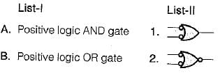
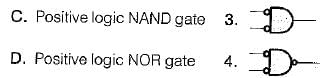
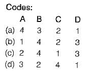
 Match List-I (Logic gates) with List-ll (Symbols) and select the correct answer using the codes given below the lists

Detailed Solution for Test: Logic Gates & Switching Circuits- 1 - Question 1
  • Positive logic AND gate is equivalent to bubbled NOR gate.
  • Positive logic OR gate is equivalent to bubbled NAND gate.
  • Positive logic NAND gate is equivalent to bubbled OR gate.
  • Positive logic NOR gate is equivalent to bubbled AND gate.
Test: Logic Gates & Switching Circuits- 1 - Question 2

The minimum number of NAND gate required to implement the logic function given by   is

Detailed Solution for Test: Logic Gates & Switching Circuits- 1 - Question 2

 can be implemented using 4 NAND gates as shown below:

Test: Logic Gates & Switching Circuits- 1 - Question 3

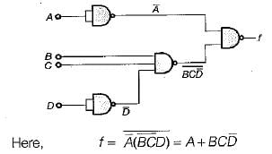
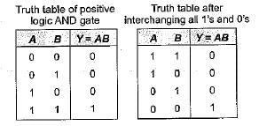
Assertion (A): When Os and 1s are interchanged in the truth table, the positive logic AND gate becomes negative logic OR gate, and positive logic NAND gate becomes negative logic NOR gate.
Reason (R): The simple method of converting the logic designation (i.e. from positive to negative logic or vice versa) is that all 0’s are replaced with 1s and all 1s with Os in the truth table.

Detailed Solution for Test: Logic Gates & Switching Circuits- 1 - Question 3

Thus, we see that after interchanging all 1’s and 0’s of inputs in the truth table of positive logic AND gate, the resulting truth table obtained is the truth table of negative logic OR gate. Similarly, we can prove that if all 0’s and 1's inputs in the truth table of NAND gate are interchanged, then the gate becomes negative logic NOR gate. Hence, both assertion and reason are true and reason is the correct explanation of assertion.

Test: Logic Gates & Switching Circuits- 1 - Question 4

 Match List-I (Logic gates) with List-ll (Applications) and select the correct answer using the codes given below the lists:

List-i
A. Exclusive OR gate
B. NOT gate
C. Exclusive NOR gate
D. NOR gate

List-ll
1. As a controlled inverter
2. As an universal gate
3. Complementation
4. Even-odd parity check

Detailed Solution for Test: Logic Gates & Switching Circuits- 1 - Question 4
  • EX-OR gate can be used as a controlled inverter as shown below:

For control input = 1 , 

For control input = 0, Y = A

  • NOT gate is basically used as an inverter or for complementation purposes.
  • EX-NOR gate can be used as even-odd parity checker because the output of EX- NOR gate is 1 if the number of 1’s in its inputs is even; if the number of 1’s is odd, the output is 0.
  • NOR gate is an universal gate.
Test: Logic Gates & Switching Circuits- 1 - Question 5

Assertion (A): The EX-NOR gate can be used as a "one-bit comparator.

Reason (R): The output of the EX-NOR gate is high if the number of high inputs to it is even while the output is low if the number of high inputs to it is odd.

Detailed Solution for Test: Logic Gates & Switching Circuits- 1 - Question 5

The solution to the assertion and reason question is as follows:

  • The EX-NOR gate functions as a one-bit comparator because it outputs high when both its inputs are the same.

  • The reason provided states that the EX-NOR gate outputs high if the number of high inputs is even and low if the number is odd. This is true but not why it works as a comparator.

  • Therefore, both the assertion and reason are true, but the reason is not the correct explanation for the assertion.

Test: Logic Gates & Switching Circuits- 1 - Question 6

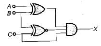
Consider the following logic circuit: What is the required input condition (A, B, C) to make the output X = 1, for the above logic circuit

Detailed Solution for Test: Logic Gates & Switching Circuits- 1 - Question 6

Here, (0, 1, 1) gives the output X = 1

Test: Logic Gates & Switching Circuits- 1 - Question 7

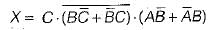
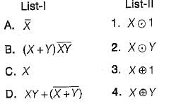
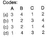
 Match List-I (Logic expression) with List-ll (Equivalent expression) and select the correct answer using the codes given below the lists:

Detailed Solution for Test: Logic Gates & Switching Circuits- 1 - Question 7

Test: Logic Gates & Switching Circuits- 1 - Question 8

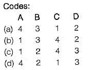
The code where all successive numbers differ from their preceding number by single bit is __________ 

Detailed Solution for Test: Logic Gates & Switching Circuits- 1 - Question 8

The numbers that differ by only a single bit from their preceding number are represented using the Gray code. Here is why Gray code is used:

  • Gray code ensures that only one bit changes at a time, reducing the chance of errors during transitions.
  • This property is important in systems where changes from one state to another should be smooth and error-free.
  • Commonly used in rotary encoders and digital communication to ensure data integrity.
Test: Logic Gates & Switching Circuits- 1 - Question 9

Which of the following logic gate follow both commutative and associate law?

Detailed Solution for Test: Logic Gates & Switching Circuits- 1 - Question 9

The AND gate follows both the commutative and associative laws. Here's why:

  • The commutative law means that the order of inputs does not change the output. For an AND gate: A & B = B & A.
  • The associative law allows grouping of inputs without affecting the result. For an AND gate: (A & B) & C = A & (B & C).

Therefore, the AND gate is the correct option as it satisfies both laws.

Test: Logic Gates & Switching Circuits- 1 - Question 10

What is a Latch? 

Detailed Solution for Test: Logic Gates & Switching Circuits- 1 - Question 10

A latch is a type of digital storage device used to store one bit of data. It is a fundamental building block in digital electronics.

  • Latches are commonly used in circuits to maintain a state until changed by an input signal.
  • They differ from flip-flops, which are more complex and triggered by clock signals.
  • A D-type latch holds a value with a single data input and a control signal.

Latches play a crucial role in memory devices and data storage operations in computing systems.

26 docs|247 tests
Information about Test: Logic Gates & Switching Circuits- 1 Page
In this test you can find the Exam questions for Test: Logic Gates & Switching Circuits- 1 solved & explained in the simplest way possible. Besides giving Questions and answers for Test: Logic Gates & Switching Circuits- 1, EduRev gives you an ample number of Online tests for practice
Download as PDF