Electrical Engineering (EE) Exam  >  Electrical Engineering (EE) Tests  >  GATE Electrical Engineering (EE) Mock Test Series 2025  >  Test: Modelling of Control Systems - 1 - Electrical Engineering (EE) MCQ

Test: Modelling of Control Systems - 1 - Electrical Engineering (EE) MCQ


Test Description

10 Questions MCQ Test GATE Electrical Engineering (EE) Mock Test Series 2025 - Test: Modelling of Control Systems - 1

Test: Modelling of Control Systems - 1 for Electrical Engineering (EE) 2024 is part of GATE Electrical Engineering (EE) Mock Test Series 2025 preparation. The Test: Modelling of Control Systems - 1 questions and answers have been prepared according to the Electrical Engineering (EE) exam syllabus.The Test: Modelling of Control Systems - 1 MCQs are made for Electrical Engineering (EE) 2024 Exam. Find important definitions, questions, notes, meanings, examples, exercises, MCQs and online tests for Test: Modelling of Control Systems - 1 below.
Solutions of Test: Modelling of Control Systems - 1 questions in English are available as part of our GATE Electrical Engineering (EE) Mock Test Series 2025 for Electrical Engineering (EE) & Test: Modelling of Control Systems - 1 solutions in Hindi for GATE Electrical Engineering (EE) Mock Test Series 2025 course. Download more important topics, notes, lectures and mock test series for Electrical Engineering (EE) Exam by signing up for free. Attempt Test: Modelling of Control Systems - 1 | 10 questions in 30 minutes | Mock test for Electrical Engineering (EE) preparation | Free important questions MCQ to study GATE Electrical Engineering (EE) Mock Test Series 2025 for Electrical Engineering (EE) Exam | Download free PDF with solutions
Test: Modelling of Control Systems - 1 - Question 1

The electrical time-constant of an armature- controlled dc servomotor is

Test: Modelling of Control Systems - 1 - Question 2

A mass spring system under equilibrium condition is shown in figure below.

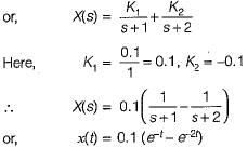
The output displacement x(t) for M = 10 kg is given by

Detailed Solution for Test: Modelling of Control Systems - 1 - Question 2

The differential equation for the given system is 

or, 
Taking Laplace transform on both sides, we get: (10s2 + 30s + 20) X(s) = 1
or, 
or, 

1 Crore+ students have signed up on EduRev. Have you? Download the App
Test: Modelling of Control Systems - 1 - Question 3

Two wheels are mechanically coupled as shown in figure below.

Here, ω1 and ω2 = angular velocities (in rad/s)
T1 and T2 = Torque (in N-m)
r1 and r2 = radius of the wheels (in cm)
θ1 and θ2 = angular displacements (in degrees)
N1, and N2 = No. of teeths on wheels
It is given that ω1 = 10 rad/s, N1 = 40, N2 - 20,
T1 = 5 N-m, r1 = 20 cm and θ1 = 20°.
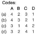
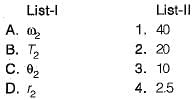
Match List-I with List-ll and select the correct answer using the codes given below the lists: 
Detailed Solution for Test: Modelling of Control Systems - 1 - Question 3

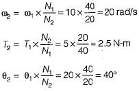
We know that,


Test: Modelling of Control Systems - 1 - Question 4

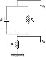
The poles-and zeros of the transfer function  for the mechanical system shown below are respectively

Detailed Solution for Test: Modelling of Control Systems - 1 - Question 4

The differential equation for the given mechanical system is

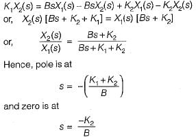
Taking Laplace transform on both sides, we get

Test: Modelling of Control Systems - 1 - Question 5

Consider the mechanical system shown in figure below. 

Which one of the following circuits shows the force-voltage analogous electrical circuit for the mechanical diagram shown above?

Detailed Solution for Test: Modelling of Control Systems - 1 - Question 5


Thus, option (d) will be the correct circuit.

Test: Modelling of Control Systems - 1 - Question 6

Match List-I with List-II and select the correct answer using the codes given below the lists:
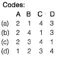
Detailed Solution for Test: Modelling of Control Systems - 1 - Question 6

For mechanical rotational system, we have: 

For electrical system, we have

Comparing equations (i) and (ii), we have:

Test: Modelling of Control Systems - 1 - Question 7

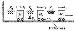
Consider the mechanical system shown below:

The system is described by the differential equations:

Detailed Solution for Test: Modelling of Control Systems - 1 - Question 7

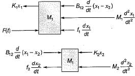
The free-body diagram for the two masses will be shown as below.

Hence, the differential equations for the two masses can be written as follows:

Test: Modelling of Control Systems - 1 - Question 8

Which of the following is not a desirable property of a servomotor in feedback control systems?

Detailed Solution for Test: Modelling of Control Systems - 1 - Question 8

Relation between electrical control system and rotor speed should be linear.

Test: Modelling of Control Systems - 1 - Question 9

Consider the following statements related to A.C. servomotors compared to D.C. servomotor used in control system applications.
1. It has less efficiency.
2. It is maintenance free.
3. It gives smooth operation.
4. It gives high power output.

Which of these statements is/are true regarding an A.C. servomotor?

Detailed Solution for Test: Modelling of Control Systems - 1 - Question 9

An A.C. servomotor doesn’t require brushes compared to a D.C. servomotor. So, it gives maintenance free operation. It’s efficiency is less due to low power output but, gives smooth operation.

Test: Modelling of Control Systems - 1 - Question 10

A field controlled DC servomotor is a

25 docs|247 tests
Information about Test: Modelling of Control Systems - 1 Page
In this test you can find the Exam questions for Test: Modelling of Control Systems - 1 solved & explained in the simplest way possible. Besides giving Questions and answers for Test: Modelling of Control Systems - 1, EduRev gives you an ample number of Online tests for practice

Up next

Download as PDF

Up next