Electronics and Communication Engineering (ECE) Exam  >  Electronics and Communication Engineering (ECE) Tests  >  GATE ECE (Electronics) Mock Test Series 2025  >  Test: Modelling of Control Systems- 2 - Electronics and Communication Engineering (ECE) MCQ

Test: Modelling of Control Systems- 2 - Electronics and Communication Engineering (ECE) MCQ


Test Description

15 Questions MCQ Test GATE ECE (Electronics) Mock Test Series 2025 - Test: Modelling of Control Systems- 2

Test: Modelling of Control Systems- 2 for Electronics and Communication Engineering (ECE) 2024 is part of GATE ECE (Electronics) Mock Test Series 2025 preparation. The Test: Modelling of Control Systems- 2 questions and answers have been prepared according to the Electronics and Communication Engineering (ECE) exam syllabus.The Test: Modelling of Control Systems- 2 MCQs are made for Electronics and Communication Engineering (ECE) 2024 Exam. Find important definitions, questions, notes, meanings, examples, exercises, MCQs and online tests for Test: Modelling of Control Systems- 2 below.
Solutions of Test: Modelling of Control Systems- 2 questions in English are available as part of our GATE ECE (Electronics) Mock Test Series 2025 for Electronics and Communication Engineering (ECE) & Test: Modelling of Control Systems- 2 solutions in Hindi for GATE ECE (Electronics) Mock Test Series 2025 course. Download more important topics, notes, lectures and mock test series for Electronics and Communication Engineering (ECE) Exam by signing up for free. Attempt Test: Modelling of Control Systems- 2 | 15 questions in 45 minutes | Mock test for Electronics and Communication Engineering (ECE) preparation | Free important questions MCQ to study GATE ECE (Electronics) Mock Test Series 2025 for Electronics and Communication Engineering (ECE) Exam | Download free PDF with solutions
Test: Modelling of Control Systems- 2 - Question 1

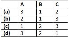
Match List - I (Control system components) with List - II (Principle of operation) and select the correct answer using the codes given below the lists:
List - I
A. Synchronous
B. Potentiometer
C. Tachometer
List - lI
1. Mechanical displacement into electrical energy.
2. Angular position of a shaft into an electrical signal.
3. Electrical output proportional to speed.
Codes:
Test: Modelling of Control Systems- 2 - Question 2

An a.c. servomotor

1 Crore+ students have signed up on EduRev. Have you? Download the App
Test: Modelling of Control Systems- 2 - Question 3

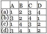
Match List - I (Control System Components) with List - II (Applications) and select the correct answer using the codes given below the lists:
List - I
A. Stepper Motors
B. Synchros
C. Servomotors
D. Potentiometer
List - II
1. Radars, electromechanical actuators.
2. Displacement transducer
3. Printers, Watches
4. Detectors and encoders
Codes:
Test: Modelling of Control Systems- 2 - Question 4

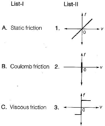
Match List - I (Types of friction) with List - II (Corresponding frictional force vs Velocity curve) and select the correct answer using the codes given below the lists:
Detailed Solution for Test: Modelling of Control Systems- 2 - Question 4

let's analyze the characteristics of each type of friction:

  1. Static friction (A) - This type of friction occurs when there is no relative motion between the surfaces in contact. The frictional force increases up to a maximum value as the applied force increases, and it equals the applied force until motion starts. After this point, it transitions to kinetic friction. This corresponds to a frictional force that stays at zero until the velocity starts changing.
  2. Coulomb friction (B) - Also known as kinetic or dry friction, this type of friction remains constant regardless of the velocity once the object is in motion. It is independent of the velocity of the moving surfaces. This corresponds to a horizontal line for the frictional force versus velocity curve.
  3. Viscous friction (C) - This type of friction is proportional to the velocity. The frictional force increases linearly with the velocity. This corresponds to a linear relationship between frictional force and velocity.

Now, match these characteristics with the curves in List-II:

  • Curve 1 shows a frictional force that increases linearly with velocity. This corresponds to Viscous friction.
  • Curve 2 shows a constant frictional force regardless of the velocity. This corresponds to Coulomb friction.
  • Curve 3 shows a frictional force that is zero until a certain point (indicating no movement) and then jumps to a certain value once motion starts. This corresponds to Static friction.

So, the correct matching is:

  • A: 3 (Static friction)
  • B: 2 (Coulomb friction)
  • C: 1 (Viscous friction)

The correct answer is (d): 3 2 1

Test: Modelling of Control Systems- 2 - Question 5

Assertion (A): D’Alembert’s principle states that “for any- body, the algebraic sum of externally applied forces and the forces resisting motion in any given direction is zero.
”Reason (R): D’Alembert principle is used in writing the equation of motion of mechanical systems.

Detailed Solution for Test: Modelling of Control Systems- 2 - Question 5

Both assertion and reason are true. However, the correct reason is that all the forces in the direction of reference direction are considered as positive and the forces opposite to the reference direction are taken as negative due to which the algebraic sum of forces is zero.

Test: Modelling of Control Systems- 2 - Question 6

Assertion (A): When two time constant elements are cascaded interactively, the overall transfer function of such an arrangement is the product of two individual transfer functions.
Reason (R): There is loading effect present in such an arrangement.

Detailed Solution for Test: Modelling of Control Systems- 2 - Question 6

When two time constant elements are cascaded non-interactively, then the overall transfer function is the product of two individual TFs.
Hence, assertion is false.

Test: Modelling of Control Systems- 2 - Question 7

Assertion (A): An a.c. servomotor used in control system applications must have high starting torque and low inertia.
Reason (R): A large value of rotor diameter and small axial length gives a higher value of starting torque and a low value of inertia.

Detailed Solution for Test: Modelling of Control Systems- 2 - Question 7

Reason is a false statement because small diameter and large axial length will give a lower value of inertia of motor.

Test: Modelling of Control Systems- 2 - Question 8

Assertion (A): When the rotor of the synchro is inclined along any one of the stator axis completely, then this position is called electrical zero position.
Reason (R): When the rotor of the synchro is inclined along any one of the stator axis completely, then maximum voltage will be induced in that winding and almost zero voltage will be induced in the other two windings.

Test: Modelling of Control Systems- 2 - Question 9

Assertion (A): Stepper motors can be used for speed control.
Reason (R): The motor speed is proportional to the rate of command pulses.

Detailed Solution for Test: Modelling of Control Systems- 2 - Question 9

Stepper motors can be used for speed control because the motor speed is proportional to the rate of command pulses.

Test: Modelling of Control Systems- 2 - Question 10

The stator of the synchros is made of

Test: Modelling of Control Systems- 2 - Question 11

A synchro is used to

Test: Modelling of Control Systems- 2 - Question 12

A synchro transmitter-receiver unit is a

Test: Modelling of Control Systems- 2 - Question 13

The transfer function of a tachometer is of the form

Test: Modelling of Control Systems- 2 - Question 14

In force-current analogy stiffness constant K is analogous to

Detailed Solution for Test: Modelling of Control Systems- 2 - Question 14


and 

Test: Modelling of Control Systems- 2 - Question 15

In liquid level systems, the units of capacitance of a tank is

Detailed Solution for Test: Modelling of Control Systems- 2 - Question 15

If q = flow; A = Area of cross-section and h = height of water in tank.

On comparing equations (i) and (ii), we have C (Farad) = A = m2

25 docs|263 tests
Information about Test: Modelling of Control Systems- 2 Page
In this test you can find the Exam questions for Test: Modelling of Control Systems- 2 solved & explained in the simplest way possible. Besides giving Questions and answers for Test: Modelling of Control Systems- 2, EduRev gives you an ample number of Online tests for practice

Top Courses for Electronics and Communication Engineering (ECE)

Download as PDF

Top Courses for Electronics and Communication Engineering (ECE)