Electrical Engineering (EE) Exam  >  Electrical Engineering (EE) Tests  >  GATE Electrical Engineering (EE) Mock Test Series 2025  >  Test: Signal Flow Graphs - 1 - Electrical Engineering (EE) MCQ

Test: Signal Flow Graphs - 1 - Electrical Engineering (EE) MCQ


Test Description

15 Questions MCQ Test GATE Electrical Engineering (EE) Mock Test Series 2025 - Test: Signal Flow Graphs - 1

Test: Signal Flow Graphs - 1 for Electrical Engineering (EE) 2024 is part of GATE Electrical Engineering (EE) Mock Test Series 2025 preparation. The Test: Signal Flow Graphs - 1 questions and answers have been prepared according to the Electrical Engineering (EE) exam syllabus.The Test: Signal Flow Graphs - 1 MCQs are made for Electrical Engineering (EE) 2024 Exam. Find important definitions, questions, notes, meanings, examples, exercises, MCQs and online tests for Test: Signal Flow Graphs - 1 below.
Solutions of Test: Signal Flow Graphs - 1 questions in English are available as part of our GATE Electrical Engineering (EE) Mock Test Series 2025 for Electrical Engineering (EE) & Test: Signal Flow Graphs - 1 solutions in Hindi for GATE Electrical Engineering (EE) Mock Test Series 2025 course. Download more important topics, notes, lectures and mock test series for Electrical Engineering (EE) Exam by signing up for free. Attempt Test: Signal Flow Graphs - 1 | 15 questions in 10 minutes | Mock test for Electrical Engineering (EE) preparation | Free important questions MCQ to study GATE Electrical Engineering (EE) Mock Test Series 2025 for Electrical Engineering (EE) Exam | Download free PDF with solutions
Test: Signal Flow Graphs - 1 - Question 1

A signal flow graph is the graphical representation of the relationships between the variables of set linear algebraic equations.

Detailed Solution for Test: Signal Flow Graphs - 1 - Question 1

Explanation: By definition signal flow graphs are the graphical representation of the relationships between the variables of set linear algebraic equations.

Test: Signal Flow Graphs - 1 - Question 2

A node having only outgoing branches.

Detailed Solution for Test: Signal Flow Graphs - 1 - Question 2

Explanation: Nodes are the point by which the branches are outgoing or ingoing and this can be input or output node and input node is the node having only outgoing branches.

1 Crore+ students have signed up on EduRev. Have you? Download the App
Test: Signal Flow Graphs - 1 - Question 3

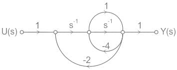
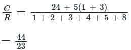
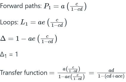
Use mason’s gain formula to find the transfer function of the given signal flow graph:

Detailed Solution for Test: Signal Flow Graphs - 1 - Question 3

Explanation: Using mason’s gain formula transfer function from signal flow graph can be calculated which relates the forward path gain to the various paths and loops.

Test: Signal Flow Graphs - 1 - Question 4

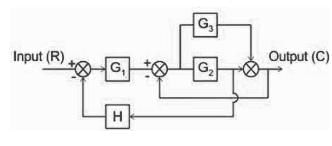
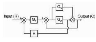
What will be the transfer function of the given block diagram?
Detailed Solution for Test: Signal Flow Graphs - 1 - Question 4


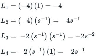
Forward path: G1 G2, G1 G3

Loops: -G2, -G1G2H, -G3

Finding the transfer function using Mason's gain formula:

Test: Signal Flow Graphs - 1 - Question 5

Loop which do not possess any common node are said to be ___________ loops.

Detailed Solution for Test: Signal Flow Graphs - 1 - Question 5

Explanation: Loop is the part of the network in which the branch starts from the node and comes back to the same node and non touching loop must not have any node in common.

Test: Signal Flow Graphs - 1 - Question 6

Signal flow graphs:

Detailed Solution for Test: Signal Flow Graphs - 1 - Question 6

Explanation: Signal flow graphs are used to find the transfer function of control system by converting the block diagrams into signal flow graphs or directly but cannot be used for nonlinear systems.

Test: Signal Flow Graphs - 1 - Question 7

Signal flow graphs are reliable to find transfer function than block diagram reduction technique.

Detailed Solution for Test: Signal Flow Graphs - 1 - Question 7

Explanation: As one set technique and formula is used here but in block diagram technique various methods are involved which increases complexity.

Test: Signal Flow Graphs - 1 - Question 8

The relationship between an input and output variable of a signal flow graph is given by the net gain between the input and output node is known as the overall______________

Detailed Solution for Test: Signal Flow Graphs - 1 - Question 8

Explanation: The relationship between input and output variable of a signal flow graph is the overall gain of the system.

Test: Signal Flow Graphs - 1 - Question 9

Loop which do not possess any common node are said to be ___________ loops.

Detailed Solution for Test: Signal Flow Graphs - 1 - Question 9

Explanation: Loop is the part of the network in which the branch starts from the node and comes back to the same node and non touching loop must not have any node in common.

Test: Signal Flow Graphs - 1 - Question 10

Signal flow graphs:

Detailed Solution for Test: Signal Flow Graphs - 1 - Question 10

Explanation: Signal flow graphs are used to find the transfer function of control system by converting the block diagrams into signal flow graphs or directly but cannot be used for nonlinear systems.

Test: Signal Flow Graphs - 1 - Question 11

Signal flow graphs are reliable to find transfer function than block diagram reduction technique.

Detailed Solution for Test: Signal Flow Graphs - 1 - Question 11

Explanation: As one set technique and formula is used here but in block diagram technique various methods are involved which increases complexity.

Test: Signal Flow Graphs - 1 - Question 12

The relationship between an input and output variable of a signal flow graph is given by the net gain between the input and output node is known as the overall______________

Detailed Solution for Test: Signal Flow Graphs - 1 - Question 12

Explanation: The relationship between input and output variable of a signal flow graph is the overall gain of the system.

Test: Signal Flow Graphs - 1 - Question 13

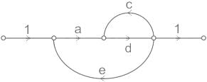
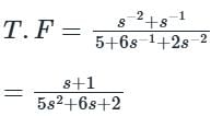
Use mason’s gain formula to calculate the transfer function of given figure:

Detailed Solution for Test: Signal Flow Graphs - 1 - Question 13

Explanation: Use mason’s gain formula to solve the signal flow graph and by using mason’s gain formula transfer function from signal flow graph can be calculated which relates the forward path gain to the various paths and loops.

Test: Signal Flow Graphs - 1 - Question 14

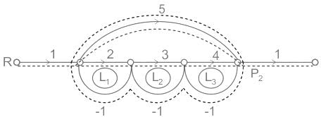
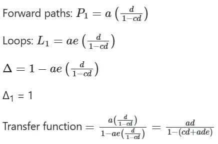
Use mason’s gain formula to find the transfer function of the given figure:
  

Detailed Solution for Test: Signal Flow Graphs - 1 - Question 14

Explanation: Using mason’s gain formula transfer function from signal flow graph can be calculated which relates the forward path gain to the various paths and loops.

Test: Signal Flow Graphs - 1 - Question 15

A node having only outgoing branches.

Detailed Solution for Test: Signal Flow Graphs - 1 - Question 15

Nodes are the point by which the branches are outgoing or ingoing and this can be input or output node and input node is the node having only outgoing branches.

25 docs|247 tests
Information about Test: Signal Flow Graphs - 1 Page
In this test you can find the Exam questions for Test: Signal Flow Graphs - 1 solved & explained in the simplest way possible. Besides giving Questions and answers for Test: Signal Flow Graphs - 1, EduRev gives you an ample number of Online tests for practice

Up next

Download as PDF

Up next