1 Crore+ students have signed up on EduRev. Have you? |
SCRs with a peak forward rating of 2 kV and an average on-state current rating of 50 A are used in a single-phase mid-point converter. If the factor of safety is 2.5, the power that can be handled by this converter is ______kW
The maximum voltage across SCRs in mod point connection is 2 Vm. So the maximum voltage of SCR = = 400 V
The maximum average power that the midpoint converter can handle is
= 12.732 kW
In a center tap full wave rectifier, if the peak voltage applied between the center tap and one of the secondary 200 V, then the reverse biased diode is applied with a maximum voltage of:
Concept:
Peak inverse voltage: It is a voltage across the diode when it is reversed bias.
The following circuit is the center tapped full-wave rectifier.
Consider for positive half cycle, D1 is FB and D2 is reversed biased.
In loop 1, Apply KVL
⇒ V0 = Vin
Now, apply KVL in loop 2
Vin + V0 = VD2
⇒ VD2 = Vin + Vin = 2Vin
PIV of the centre tapped full wave rectifier = 2Vin
Calculation:
Given that, the center-tapped full-wave rectifier and Vin = 200 V (Peak) between the centre tap and one end of secondary.
Peak inverse voltage = 2Vin = 400 V
A full-wave rectifier uses 2 diodes. The internal resistance of each diode is 20 Ω. The transformer RMS secondary voltage from centre tap to each end of the secondary is 50 V and the load resistance is 980 Ω. Mean load current will be
Concept:
Center tapped full wave rectifier:
Analysis: The DC output voltage or average output voltage can be calculated as follows,
V0 = 2Vm / π
Now we can calculate the average or mean current of load by dividing the average load voltage by load resistance RL. Therefore mean load current is given by
I0 = V0 / RL
If the internal resistance of the diode is given in that case mean load current I0 = V0 / (RL + r)
Where r = internal resistance of the diode.
Calculation:
Given that
Rms value of supply voltage V = 50 V
The internal resistance of diode r = 20 Ω
The load resistance RL = 980 Ω
Maximum voltage on the secondary side Vm = √2 V = √2 × 50 = 70.7 V
Average or DC output voltage V0 = (2 × 70.7) / π = 45 V
Average or mean load current is
I0 = V0 / (RL + r) = 45 /(980 + 20) = 45 mA
In a two-diode full wave rectifier, with a load current requirement of 4.2 A, what should be the current ratings of the diodes used?
Concept:
Center tapped full wave rectifier:
Analysis:
The DC output voltage or average output voltage can be calculated as follows,
V0 = 2Vm / π
Now we can calculate the average or mean current of load by dividing the average load voltage by load resistance RL. Therefore mean load current is given by
I0 = V0 / RL
Current through each diode will be half of the load current, as each diode conducts only for the half cycle.
Calculation:
Load current = I0 = 4.2 A
Current through each diode = I0 / 2 = 4.2 / 2 = 2.1 A
∴The current ratings of the each diode is 2.1 A.
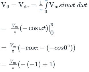
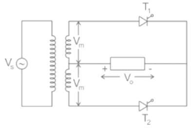
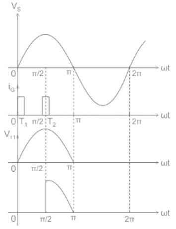
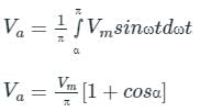
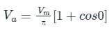
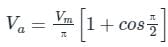
A single-phase mid-point full-wave SCR converter with maximum mid-point voltage of Vm volts develops an average output voltage across a resistive load at firing delay angles of 0 and π/2 rad., respectively, as
A single-phase mid-point full-wave SCR converter:
In this circuit, two thyristors are used and are connected as shown below
Where,
Vs is the source voltage
Vm is the maximum voltage of the midpoint
Let α be the firing angle
V0 is the output voltage
When the thyristors are triggered with a firing angle 0 and π/2
Then the output waveform will be as follows
Let the average output voltage of the circuit be Va
The value of source voltage is Vm sin ωt
Calculation:
Given,
α1 = 0, α2 = π/2
For the first thyristor, the average output voltage is
Va = 2Vm / π
For the second thyristor, the average output voltage is
Va = Vm / π
In a 12 phase full wave rectifier if source frequency is 30 Hz, then the ripple frequency will be_____Hz
We know that
Ripple frequency = 2nf = 2 × 12 × 30 = 720 Hz
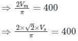
A single-phase AC supply is connected to a full wave rectifier through a transformer. The rectifier is required to supply an average DC output voltage of Vdc = 400 V to a resistive load of R = 10 Ω. The kVA rating of the transformer is __________ (in kVA)
Concept:
In a full wave rectifier though a transformer,
Average output voltage, V0 = 2Vm/π
Average output current, I0 = V0/R
RMS value of output voltage Vor = Vs
RMS value of load current, Ior = Vs/R
Average value of diode current, Id = Im/2
RMS value of diode current, Idr = Ior
Peak value of diode current, Idm = √2 Ior
Power delivered to the load = Vor Ior
Input voltamperes = Vs Ior
Calculation:
Given that, DC output voltage (VDC) = 400 V
Average output voltage of rectifier (V0) = 400 V
⇒ Vs = 444.28 V
Load resistance (R) = 10 Ω
RMS value of load current, Ior = 444.2810 = 44.428A
kVA rating of transformer = 444.28 × 44.428 = 19.738 kVA
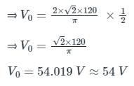
A single-phase full-wave controlled rectifier, operating at 120 V rms and 60 Hz ac supply, has a firing angle of 60°. The average value of its output voltage is
Concept:
The average output voltage of the single-phase full-wave rectifier with a resistive load is given by
V0 = 2Vm/π cos α
Where,
Vm = peak value of source voltage
α = firing angle
Calculation:
Given that:
Source voltage Vs = 120 V rms
firing angle α = 600
From the source voltage peak value Vm = √2 × 120 V
The average output value of a single-phase full-wave rectifier is given by
A 1ϕ full wave converter with RLE load wit R = 10Ω, L = 8mH and E = 150V. The AC voltage source is 230V, 50Hz for continuous conduction. Find the average value of load current for firing angle delay of 120°.
Concept:
The average output voltage of a 1ϕ full wave converter is given by:
Case 1: α ≤ 90°
Vo(avg) = IoR + E
This is a motoring mode of operation of a rectifier.
Case 2: α ≥ 90°
Vo(avg) = IoR - E
This is a generating mode of operation of a rectifier.
In generating mode, the polarity of battery voltage gets reversed.
Calculation:
Given, α = 120°
Io = 4.64 A
An AC voltage of maximum value equal to 100V is applied to a single-phase fully controlled bridge circuit. The peak inverse voltage rating of each SCR used will be ______.
Concept:
Single-phase fully controlled bridge circuit:
Calculation:
Given that
Vm = 100 V (AC signal)
PIV of bridge Rectifier = PIV of SCR T1 and T3 = Vm = 100 V
Similarly, PIV of SCR T2 and T2 is Vm = 100 V.
i.e. PIV of each SCR T1, T2, T3, T4 is Vm = 100 V
5 videos|39 docs|63 tests
|
Use Code STAYHOME200 and get INR 200 additional OFF
|
Use Coupon Code |
5 videos|39 docs|63 tests
|
|
|
|
|
|
|
|
|
|