Electrical Engineering (EE) Exam  >  Electrical Engineering (EE) Tests  >  Topicwise Question Bank for Electrical Engineering  >  Test: Sinusoidal Steady-State Analysis - 1 - Electrical Engineering (EE) MCQ

Test: Sinusoidal Steady-State Analysis - 1 - Electrical Engineering (EE) MCQ


Test Description

10 Questions MCQ Test Topicwise Question Bank for Electrical Engineering - Test: Sinusoidal Steady-State Analysis - 1

Test: Sinusoidal Steady-State Analysis - 1 for Electrical Engineering (EE) 2025 is part of Topicwise Question Bank for Electrical Engineering preparation. The Test: Sinusoidal Steady-State Analysis - 1 questions and answers have been prepared according to the Electrical Engineering (EE) exam syllabus.The Test: Sinusoidal Steady-State Analysis - 1 MCQs are made for Electrical Engineering (EE) 2025 Exam. Find important definitions, questions, notes, meanings, examples, exercises, MCQs and online tests for Test: Sinusoidal Steady-State Analysis - 1 below.
Solutions of Test: Sinusoidal Steady-State Analysis - 1 questions in English are available as part of our Topicwise Question Bank for Electrical Engineering for Electrical Engineering (EE) & Test: Sinusoidal Steady-State Analysis - 1 solutions in Hindi for Topicwise Question Bank for Electrical Engineering course. Download more important topics, notes, lectures and mock test series for Electrical Engineering (EE) Exam by signing up for free. Attempt Test: Sinusoidal Steady-State Analysis - 1 | 10 questions in 30 minutes | Mock test for Electrical Engineering (EE) preparation | Free important questions MCQ to study Topicwise Question Bank for Electrical Engineering for Electrical Engineering (EE) Exam | Download free PDF with solutions
Test: Sinusoidal Steady-State Analysis - 1 - Question 1

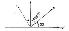
The phasor diagram shown in figure below is for a two-element series circuit having
Detailed Solution for Test: Sinusoidal Steady-State Analysis - 1 - Question 1

It is clear that i leads v by 53.2° (< 90°).
Hence the two series elements must be R and C.
∴ tan θ = tan 53.3°
tan 45° < tan 53.3° < tan 60° or,  
 1 < tan 53.3° <1.732
Hence, tan 53.3° = 1.3367

Test: Sinusoidal Steady-State Analysis - 1 - Question 2

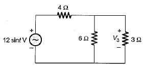
 For the circuit shown below, the voltage across the 3 Ω resistor V3 is
Detailed Solution for Test: Sinusoidal Steady-State Analysis - 1 - Question 2

Using voltage division rule, we have

Test: Sinusoidal Steady-State Analysis - 1 - Question 3

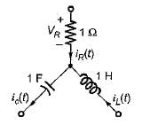
A part of a circuit shown below consists of a resistor, a capacitor and an inductor. At steady state, iR(t) = 10 sin t and vL{t) = 5 cost. The rms value of the current through the capacitor is
Detailed Solution for Test: Sinusoidal Steady-State Analysis - 1 - Question 3

Using KCL at the given node, 

Test: Sinusoidal Steady-State Analysis - 1 - Question 4

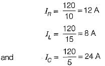
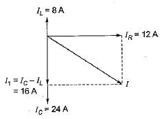
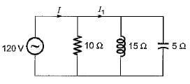
 In the circuit shown below, currents I and I1 are respectively
Detailed Solution for Test: Sinusoidal Steady-State Analysis - 1 - Question 4

From given figure

Using phasor diagram shown below, the currents I and I1 are respectively

Test: Sinusoidal Steady-State Analysis - 1 - Question 5

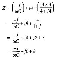
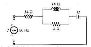
What should be the value of C for the circuit shown below such that the input power factor is unity for any frequency f of the source?
Detailed Solution for Test: Sinusoidal Steady-State Analysis - 1 - Question 5

The input impedance Z of given circuit is 

For p.f. to be unity,

Test: Sinusoidal Steady-State Analysis - 1 - Question 6

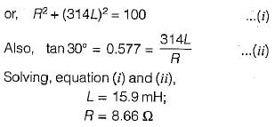
 In a series R-L circuit, the current and voltages are given by
i = cos (314t-20°) , v = 10 cos ( 314 t + 10°). The values of R and L are respectively

Detailed Solution for Test: Sinusoidal Steady-State Analysis - 1 - Question 6

Here, i lags v by 30°

also

Test: Sinusoidal Steady-State Analysis - 1 - Question 7

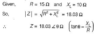
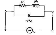
A series R-L circuit has resistance and reactance of 15 Ω and 10 Ω respectively. What should be the value of capacitor which when connected across the series combination in parallel, the system attains unity p.f.? (use f= 50 Hz)

Detailed Solution for Test: Sinusoidal Steady-State Analysis - 1 - Question 7

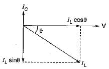
The situation is shown in figure below with it's phasor diagram.

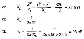
For unity p.f. operation,


Test: Sinusoidal Steady-State Analysis - 1 - Question 8

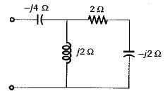
The input p.f. of the circuit shown below is
Detailed Solution for Test: Sinusoidal Steady-State Analysis - 1 - Question 8

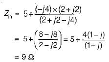
or, Zin = 2.828∠-45°Ω
Hence, input p.f. = cos45° = 0.707 (lead)

Test: Sinusoidal Steady-State Analysis - 1 - Question 9

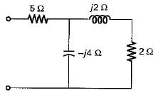
The input admittance of the circuit shown below is
Detailed Solution for Test: Sinusoidal Steady-State Analysis - 1 - Question 9

Hence

Test: Sinusoidal Steady-State Analysis - 1 - Question 10

 The driving point impedance

does not represents a passive one port network because

212 tests
Information about Test: Sinusoidal Steady-State Analysis - 1 Page
In this test you can find the Exam questions for Test: Sinusoidal Steady-State Analysis - 1 solved & explained in the simplest way possible. Besides giving Questions and answers for Test: Sinusoidal Steady-State Analysis - 1, EduRev gives you an ample number of Online tests for practice
Download as PDF