Electrical Engineering (EE) Exam  >  Electrical Engineering (EE) Tests  >  GATE Electrical Engineering (EE) Mock Test Series 2025  >  Test: Power Systems- 3 - Electrical Engineering (EE) MCQ

Test: Power Systems- 3 - Electrical Engineering (EE) MCQ


Test Description

25 Questions MCQ Test GATE Electrical Engineering (EE) Mock Test Series 2025 - Test: Power Systems- 3

Test: Power Systems- 3 for Electrical Engineering (EE) 2024 is part of GATE Electrical Engineering (EE) Mock Test Series 2025 preparation. The Test: Power Systems- 3 questions and answers have been prepared according to the Electrical Engineering (EE) exam syllabus.The Test: Power Systems- 3 MCQs are made for Electrical Engineering (EE) 2024 Exam. Find important definitions, questions, notes, meanings, examples, exercises, MCQs and online tests for Test: Power Systems- 3 below.
Solutions of Test: Power Systems- 3 questions in English are available as part of our GATE Electrical Engineering (EE) Mock Test Series 2025 for Electrical Engineering (EE) & Test: Power Systems- 3 solutions in Hindi for GATE Electrical Engineering (EE) Mock Test Series 2025 course. Download more important topics, notes, lectures and mock test series for Electrical Engineering (EE) Exam by signing up for free. Attempt Test: Power Systems- 3 | 25 questions in 75 minutes | Mock test for Electrical Engineering (EE) preparation | Free important questions MCQ to study GATE Electrical Engineering (EE) Mock Test Series 2025 for Electrical Engineering (EE) Exam | Download free PDF with solutions
Test: Power Systems- 3 - Question 1

A Δ -ΔT/F having rating 132KV/66KV, 50 MVA, the base impedance on primary side

Detailed Solution for Test: Power Systems- 3 - Question 1


Test: Power Systems- 3 - Question 2

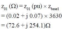
The impedance of a Δ- Y 11000/400V 3-ΔT/F of capacity 100 KVA as on its name plate as z = (0.02 + j0.07) pu. The ohmic impedance in Ωreferred to primary (11000 V) side

Detailed Solution for Test: Power Systems- 3 - Question 2

1 Crore+ students have signed up on EduRev. Have you? Download the App
Test: Power Systems- 3 - Question 3


take 6.6 KV, 20 MVA on G side, the pu impedance of line is

Detailed Solution for Test: Power Systems- 3 - Question 3


Test: Power Systems- 3 - Question 4

The sequence voltage of a 3φ system is given as

0.87 pu = Va1
-0.33 pu = Va0
-0.54 pu = Va2
What is the phase voltages on 11KV

Detailed Solution for Test: Power Systems- 3 - Question 4

Va = Va0 + Va1 + Va2 = 0
Vb = Va0 + α2Va1 + αVa2

= -0.33 + 1 ∠240 (0.87) + (1∠120) (-0.54)
= 1.232 ∠-97.69 KV
Vc = Va0 + αVal + α2Va2
= 1.317 ∠112.60 pu

Va(KV)= 0KV
Vb (KV) = Vb (pu) x KVbasd/pm
= 8.36 KV
Vc (KV) = 8.36 KV 

Test: Power Systems- 3 - Question 5

An unsymmetrical fault on a transmission line gives the sequence voltage and sequence current

Va1 = 0.837 pu
Va2 = -0.45 pu
Va0 = -0.2 pu
and sequence current I1 = I2 = I0 = -j1.2 pu. What is the type of the fault.

Detailed Solution for Test: Power Systems- 3 - Question 5

As all the sequence current is
same, fault is LG.

*Answer can only contain numeric values
Test: Power Systems- 3 - Question 6

What is fault impedance value on the base of 11KV, 20 MVA


Detailed Solution for Test: Power Systems- 3 - Question 6

Test: Power Systems- 3 - Question 7

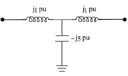
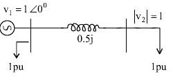
|V1| = |V2| =1pu , what is the maximum power flow in this Network.

Detailed Solution for Test: Power Systems- 3 - Question 7


= 55 pu


Notice that without capactior pr.

Test: Power Systems- 3 - Question 8

In which of the following condition the system is stable (ω is speed)

Detailed Solution for Test: Power Systems- 3 - Question 8

For stability, speed must never
be continuously increase or
decrease so

Test: Power Systems- 3 - Question 9

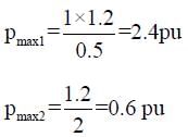
An alternator having E = 1.2 pu connected to ∞ bus through a power network. The transfer reactance between alternator and ∞ bus before fault, during fault, and after clearing fault are X1 = 0.5, X= 2.0, X3 = 1.5 pu. If initially Pm0 = Peo = 1 pu then what is δcr made by rotor such that system is stable?

Detailed Solution for Test: Power Systems- 3 - Question 9


as pm is 1 pu, which is greater than
pmax3, even if fault is cleared,
mech. input will always be
higher. System will remain
unstable.

Test: Power Systems- 3 - Question 10

A 50 bus system with 200 transmission line. How many zeroes are in Y bus matrix.

Detailed Solution for Test: Power Systems- 3 - Question 10

Test: Power Systems- 3 - Question 11

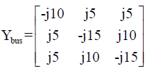
For a 3 bus network

a shunt capacitor of -j0.5 is added at 2nd bus, Y22 new = ?

Detailed Solution for Test: Power Systems- 3 - Question 11

z22 new = -j15 + j2 = -j13

Test: Power Systems- 3 - Question 12

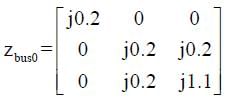
A Network having postive, negative and zero sequence bus impedance matrix as


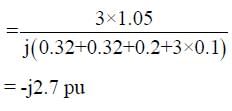
what is the LG fault current at bus 2 with zf = j0.1 pu. Pre-fault voltage at bus 2 is 1.05 pu

Detailed Solution for Test: Power Systems- 3 - Question 12


Test: Power Systems- 3 - Question 13

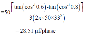
A 3φ load of 50 MW, 0.6 pf, is operating at 33KV, what is capacitance per phase required by the capacitor bank connected in Δ to improve pf to 0.8 lag.

Detailed Solution for Test: Power Systems- 3 - Question 13


Test: Power Systems- 3 - Question 14

what is reactive power support required at bus 2.

Detailed Solution for Test: Power Systems- 3 - Question 14

As at load, no imaginary term is
given. This is active power only


= -0.267
as only active load is present a
capacitor must be installed to
get reactive power zero
so, θrequired = 0.267

Test: Power Systems- 3 - Question 15

A Network containing 20 voltage controlled bus, 10 reactive power support bus, a generator bus, 5 fixed shunt capacitance bus, total voltage controlled bus is

Detailed Solution for Test: Power Systems- 3 - Question 15

Shunt capacity is not voltage
controlled bus,
Total no. of voltage controlled
bus

= 20 + 10 + (9 - 1)
= 38

Test: Power Systems- 3 - Question 16

A transmission line of length 300 km operating at 50Hz, the receiving end voltage under no load VS = 1pu is

Detailed Solution for Test: Power Systems- 3 - Question 16


Test: Power Systems- 3 - Question 17

A transmission line of length 600km, has a phase shift in degree of

Detailed Solution for Test: Power Systems- 3 - Question 17

Test: Power Systems- 3 - Question 18

A generator having H = 6 MJ/MVA is connected to generator having H = 4 MJ/MVA. A fault reduce the pr. out put to 0.6 pu which was initially 1 pu. Find angular acceleration in elect degree/S2

Detailed Solution for Test: Power Systems- 3 - Question 18


Test: Power Systems- 3 - Question 19

A transmission line has impedance (3 + j4) Ω/phase. The power factor of the load for maximum V.R.

Detailed Solution for Test: Power Systems- 3 - Question 19

For maximum V.R


= 0.6

Test: Power Systems- 3 - Question 20

A 3φ transmission line has ABCD parameters as A= 0.75 ∠0° = D, B = 100∠90°Ω, C = 0.5 x 10⁻⁶ ∠90° ℧ operating at Vs = 200 KV, VR at no load, and shunt reactor for compensating Ferranti-effect 

Detailed Solution for Test: Power Systems- 3 - Question 20


*Answer can only contain numeric values
Test: Power Systems- 3 - Question 21

In previous question, the charging current at no load is_____


Detailed Solution for Test: Power Systems- 3 - Question 21

Test: Power Systems- 3 - Question 22

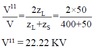
A TL has zS = 400Ω is terminated with a cable with zL = 50Ω. A rectangular pulse of 100KV is travelling towards the cable. The transmitted volt will be

Detailed Solution for Test: Power Systems- 3 - Question 22

Test: Power Systems- 3 - Question 23

A 3φ transmission line having a surge impedance of 400Ω is operating at 400 KV line is compensated with 30% of shunt capacitor at the load end. The other end is connected to a generator which is delivering power at 200 MW. SIL of the above system is

Detailed Solution for Test: Power Systems- 3 - Question 23


= 400 MW

Test: Power Systems- 3 - Question 24

In above question, SIL after compensation is

Detailed Solution for Test: Power Systems- 3 - Question 24


Test: Power Systems- 3 - Question 25

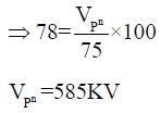
A TL supported by 3 insulation disc, the maximum voltage of each disc is 25 KV. Find the operating voltage per phase of the line given efficiency η = 78%

Detailed Solution for Test: Power Systems- 3 - Question 25


as (V1 + V2 + V3) is per phase voltage

25 docs|247 tests
Information about Test: Power Systems- 3 Page
In this test you can find the Exam questions for Test: Power Systems- 3 solved & explained in the simplest way possible. Besides giving Questions and answers for Test: Power Systems- 3, EduRev gives you an ample number of Online tests for practice

Top Courses for Electrical Engineering (EE)

Download as PDF

Top Courses for Electrical Engineering (EE)