Computer Science Engineering (CSE) Exam  >  Computer Science Engineering (CSE) Tests  >  GATE Computer Science Engineering(CSE) 2025 Mock Test Series  >  Test: Combinational Circuit- 2 - Computer Science Engineering (CSE) MCQ

Test: Combinational Circuit- 2 - Computer Science Engineering (CSE) MCQ


Test Description

15 Questions MCQ Test GATE Computer Science Engineering(CSE) 2025 Mock Test Series - Test: Combinational Circuit- 2

Test: Combinational Circuit- 2 for Computer Science Engineering (CSE) 2025 is part of GATE Computer Science Engineering(CSE) 2025 Mock Test Series preparation. The Test: Combinational Circuit- 2 questions and answers have been prepared according to the Computer Science Engineering (CSE) exam syllabus.The Test: Combinational Circuit- 2 MCQs are made for Computer Science Engineering (CSE) 2025 Exam. Find important definitions, questions, notes, meanings, examples, exercises, MCQs and online tests for Test: Combinational Circuit- 2 below.
Solutions of Test: Combinational Circuit- 2 questions in English are available as part of our GATE Computer Science Engineering(CSE) 2025 Mock Test Series for Computer Science Engineering (CSE) & Test: Combinational Circuit- 2 solutions in Hindi for GATE Computer Science Engineering(CSE) 2025 Mock Test Series course. Download more important topics, notes, lectures and mock test series for Computer Science Engineering (CSE) Exam by signing up for free. Attempt Test: Combinational Circuit- 2 | 15 questions in 45 minutes | Mock test for Computer Science Engineering (CSE) preparation | Free important questions MCQ to study GATE Computer Science Engineering(CSE) 2025 Mock Test Series for Computer Science Engineering (CSE) Exam | Download free PDF with solutions
Test: Combinational Circuit- 2 - Question 1

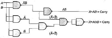
The following circuit

Can be represented as:

Detailed Solution for Test: Combinational Circuit- 2 - Question 1

From the given diagram we can see that

Test: Combinational Circuit- 2 - Question 2

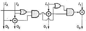
The circuit shown below converts.

Detailed Solution for Test: Combinational Circuit- 2 - Question 2

if input is 1010 it generate 1101 which is same as gray to binary code converter.

Test: Combinational Circuit- 2 - Question 3

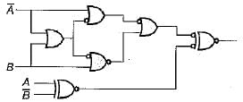
The output of the circuit shown in following figure is equal to
Detailed Solution for Test: Combinational Circuit- 2 - Question 3
  • Analyze the circuit step by step:
    • Input A̅ and B: Pass through an AND gate to produce A̅B.
    • Input A and B̅: Pass through an AND gate to produce AB̅.
    • Combine A̅B and AB̅ using an OR gate to give A̅B + AB̅.
  • A̅B + AB̅ is the Boolean expression for the XOR gate.
  • The circuit output simplifies to A⊕B.
  • Correct answer: (a) A̅B + AB̅.
Test: Combinational Circuit- 2 - Question 4

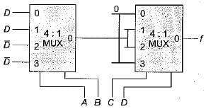
The circuit given in figure is to be used to implement the function   What is the values should be selected I and J?

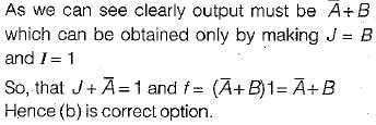
Detailed Solution for Test: Combinational Circuit- 2 - Question 4


Test: Combinational Circuit- 2 - Question 5

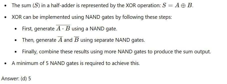
Minimum number of NAND gates required to implement sum in half-adder circuit is:

Detailed Solution for Test: Combinational Circuit- 2 - Question 5

Test: Combinational Circuit- 2 - Question 6

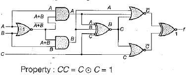
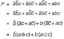
The following circuit is an implemented of:
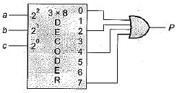
1. Sum of full adder
2. Carry of half adder
3. Difference of full subtracte

Detailed Solution for Test: Combinational Circuit- 2 - Question 6

From the given circuit


For which only 1 and 3 satisfy. Hence correct option is (d),

Test: Combinational Circuit- 2 - Question 7

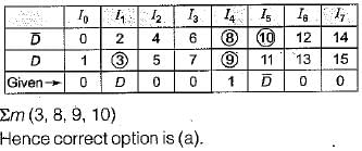
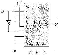
The circuit below represents function X{A, B, C, D) as:
Detailed Solution for Test: Combinational Circuit- 2 - Question 7

The given circuit represents the implementation of four variable function using 8: 1 MUX here. D as taken as the fourth i/p and A, B, C act as select lines.

Test: Combinational Circuit- 2 - Question 8

If half adders and full adders are implemented using gates, then for the addition of two 17 bit numbers (using minimum gates) the number of half adders and full adders required will be 

Detailed Solution for Test: Combinational Circuit- 2 - Question 8

As we know that n bit full adder circuit can represent (n + 1) bits sum. In order to represent addition of two 17 bits numbers we require minimum of 16 full adder and 1 half adder.
Note: For the first bit we can use either HA or FA. Hence, for addition of two 17 bit numbers inspire of 17 full adders we can perform the same task using 16 FA and 1 HA.
Hence (c) is the correct option.

Test: Combinational Circuit- 2 - Question 9

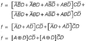
To realize following function 'f'

How many minimum number of 2 input NAND gates are required

Detailed Solution for Test: Combinational Circuit- 2 - Question 9


So it required 10 NAND gates.

Test: Combinational Circuit- 2 - Question 10

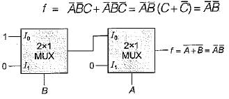
Minimum number of 2 x 1 multiplexers required to realize the following function,  Assume that inputs are available only in true forr and Boolean constants.1 and 0 are available.

Detailed Solution for Test: Combinational Circuit- 2 - Question 10

Test: Combinational Circuit- 2 - Question 11

The number of full and half-adder required to add 16-bit numbers is

Detailed Solution for Test: Combinational Circuit- 2 - Question 11

To 16 bits number, 1 half and 15 full address or 16 full address are required.

Test: Combinational Circuit- 2 - Question 12

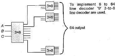
 How many 3-to-8 line decoders with an enable input are needed to construct a 6-to-64 line decoder without using any other logic gates?

Detailed Solution for Test: Combinational Circuit- 2 - Question 12

Test: Combinational Circuit- 2 - Question 13

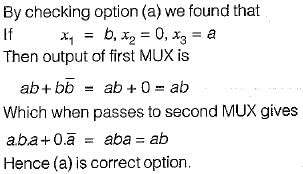
The following circuit implements a two-input AND gate using two 2-1 multiplexers.
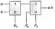
What are the values of X1 X2, X3?

Detailed Solution for Test: Combinational Circuit- 2 - Question 13


Test: Combinational Circuit- 2 - Question 14

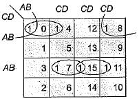
Consider excess-3 code that is used to represent integers 0 through 9 as shown below:
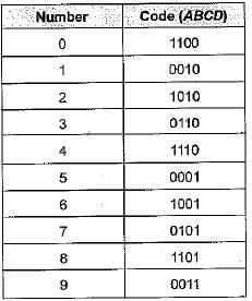
Which of the following expressions is the correct one for an invalid code?

Detailed Solution for Test: Combinational Circuit- 2 - Question 14

Invalid code words are 0, 4, 4, 8, 11, 5.

So code will be a'c'd' + b'c'd' + bed + acd.

Test: Combinational Circuit- 2 - Question 15

What logic function is performed by the circuit shown below:
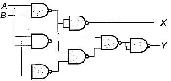
Detailed Solution for Test: Combinational Circuit- 2 - Question 15


Hence the given circuit represents Half adder.

55 docs|215 tests
Information about Test: Combinational Circuit- 2 Page
In this test you can find the Exam questions for Test: Combinational Circuit- 2 solved & explained in the simplest way possible. Besides giving Questions and answers for Test: Combinational Circuit- 2, EduRev gives you an ample number of Online tests for practice
Download as PDF