Test: Combinational Logic Circuits - 1 - Electronics and Communication Engineering (ECE) MCQ
20 Questions MCQ Test - Test: Combinational Logic Circuits - 1

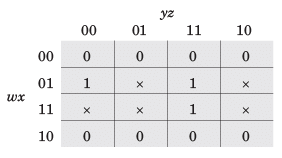
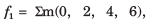
A switching function of four variable, f (w, x y, z) is to equal the product of two other function f1 and f2, of the same variable f = f1f2 . The function f and f1 are as follows :
f = ∑m(4,7,15)
f = ∑m(0,1,2, 3, 4,7, 8,9,10,11,15)
Que: The number of full specified function, that will satisfy the given condition, is
A switching function of four variable, f (w, x y, z) is to equal the product of two other function f1 and f2, of the same variable f = f1f2 . The function f and f1 are as follows :
f = ∑m(4,7,15)
f1 = ∑m(0,1,2, 3, 4,7, 8,9,10,11,15)
Que: The simplest function for f2 is


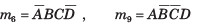
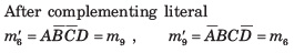
A four-variable switching function has minterms m6 and m9. If the literals in these minterms are complemented, the corresponding minterm numbers are
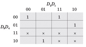
The minimum function that can detect a “divisible by 3’’ 8421 BCD code digit (representation D8 D4 D2 D1 ) is given by

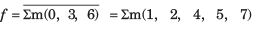
For a binary half subtractor having two input A and B, the correct set of logical expressions for the outputs D = (A - B) and X (borrow) are
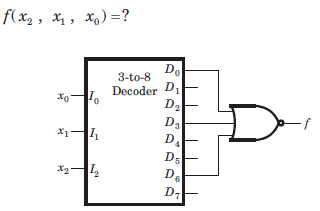
What type of logic circuit is represented by the figure shown below?
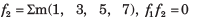
The building block shown in fig. is a active high output decoder.
Que: The output X is

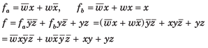
The building block shown in fig. is a active high output decoder.
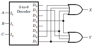
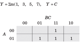
Que: The output Y is
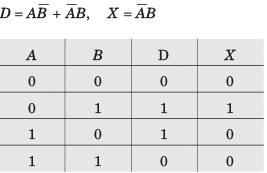
A logic circuit consist of two 2 x 4 decoder as shown in fig.
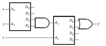
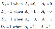
The output of decoder are as follow
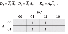
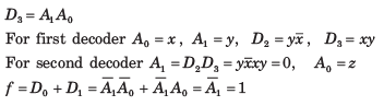
The value of f ( x, y, z) is
Number of 2 × 1 Multiplexers are required to implement 64 × 1 Multiplexers
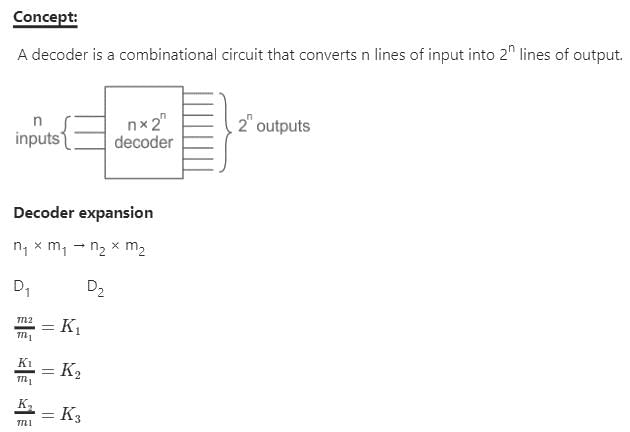
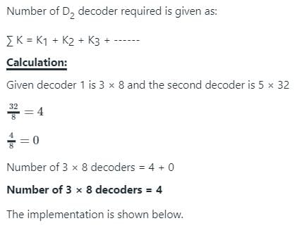
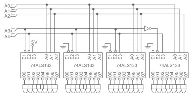
How many 3-line-to-8-line decoders are required for a 5-of-32 decoder?
Number of 2 × 1 Multiplexers are required to implement 64 × 1 Multiplexers
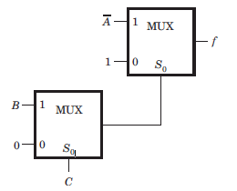
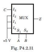
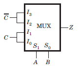
The MUX shown in fig. P4.2.31 is 4 * 1 multiplexer. The output Z is
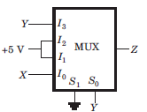
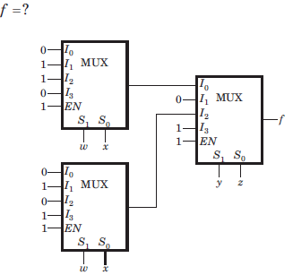
The output of the 4 x 1 multiplexer shown in fig. is
The MUX shown in fig. is a 4 x 1 multiplexer. The output Z is


For the logic circuit shown in fig.the output Y is

Important Questions for Combinational Logic Circuits - 1
Combinational Logic Circuits - 1 MCQs with Answers
Online Tests for Combinational Logic Circuits - 1
|
© EduRev
|
Education Revolution
|


|


