Electronics and Communication Engineering (ECE) Exam  >  Electronics and Communication Engineering (ECE) Tests  >  GATE ECE (Electronics) Mock Test Series 2025  >  Test: Electronic Devices - 5 - Electronics and Communication Engineering (ECE) MCQ

Test: Electronic Devices - 5 - Electronics and Communication Engineering (ECE) MCQ


Test Description

10 Questions MCQ Test GATE ECE (Electronics) Mock Test Series 2025 - Test: Electronic Devices - 5

Test: Electronic Devices - 5 for Electronics and Communication Engineering (ECE) 2025 is part of GATE ECE (Electronics) Mock Test Series 2025 preparation. The Test: Electronic Devices - 5 questions and answers have been prepared according to the Electronics and Communication Engineering (ECE) exam syllabus.The Test: Electronic Devices - 5 MCQs are made for Electronics and Communication Engineering (ECE) 2025 Exam. Find important definitions, questions, notes, meanings, examples, exercises, MCQs and online tests for Test: Electronic Devices - 5 below.
Solutions of Test: Electronic Devices - 5 questions in English are available as part of our GATE ECE (Electronics) Mock Test Series 2025 for Electronics and Communication Engineering (ECE) & Test: Electronic Devices - 5 solutions in Hindi for GATE ECE (Electronics) Mock Test Series 2025 course. Download more important topics, notes, lectures and mock test series for Electronics and Communication Engineering (ECE) Exam by signing up for free. Attempt Test: Electronic Devices - 5 | 10 questions in 30 minutes | Mock test for Electronics and Communication Engineering (ECE) preparation | Free important questions MCQ to study GATE ECE (Electronics) Mock Test Series 2025 for Electronics and Communication Engineering (ECE) Exam | Download free PDF with solutions
Test: Electronic Devices - 5 - Question 1

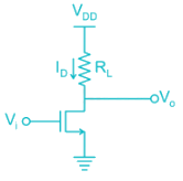
The figure shows the VTC characteristics of an NMOS inverter with three varying resistive loads (R).
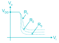

The correct statement is:

Detailed Solution for Test: Electronic Devices - 5 - Question 1

  • As Vi is increased voltage drop across RL increases and V0 decreases.
  • The sharpness of the transition region increases with the increasing load resistance.
  • Hence R3 > R2 > R1.
*Answer can only contain numeric values
Test: Electronic Devices - 5 - Question 2

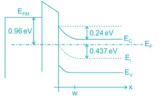
Assume that the zero for electrostatic potential is in the semiconductor bulk at large x and that there is no metal semiconductor work function difference. The relative dielectric constant for the oxide is ϵr = 11.8. If the intrinsic concentration is 1010/cm3. The doping density ND is _____ × 1017/cm3 (KT = 0.026 V)

Detailed Solution for Test: Electronic Devices - 5 - Question 2

The doping density is given by:

= 1010 e(0.437/0.026)

= 1.99 × 10¹⁷

Test: Electronic Devices - 5 - Question 3

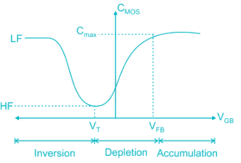
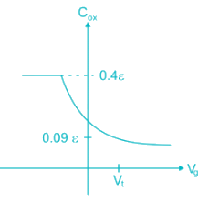
The figure shows MOS capacitor variation with applied gate voltage for n-type body/substrate.
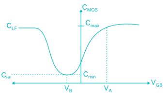
The flat band voltage is:

Detailed Solution for Test: Electronic Devices - 5 - Question 3

  • Flat band voltage is the voltage where there is no charge present in oxide or oxide-semiconductor interface. i.e. No thickness of channel
  • Cox is constant and decreased subsequently
    Note: Here, VG is negative (for PMOS)
  • Hence, voltage is decreased from positive (VFB) to negative.
*Answer can only contain numeric values
Test: Electronic Devices - 5 - Question 4

The insulator capacitance Ci of an ideal MOS capacitor with 10-nm gate oxide (εr = 3.9) on p-type Si with Na = 1016 cm-3 is ________ × 10-7 F/cm2


Detailed Solution for Test: Electronic Devices - 5 - Question 4

The insulator capacitance is the capacitance under strong accumulation

= 3.453 × 10⁻⁷ F/cm2

Test: Electronic Devices - 5 - Question 5

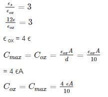
Which of the following curves represents the correct C – V characteristics of an NMOS transistor having an oxide layer thickness of 10 nm and a maximum depletion thickness of 100 nm. [Assume ϵs = permittivity of semiconductor, ϵox = permittivity of oxide and 
 

Detailed Solution for Test: Electronic Devices - 5 - Question 5

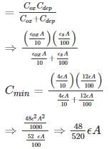
Given, tox = 10 nm, d = 100 nm

Cmin = series combination of Cox and Cdep

= 0.09 ϵA

Test: Electronic Devices - 5 - Question 6

The mobility of hole is 0.4 times the mobility of electron. What must be the ratio of width of n-channel to p-channel MOSFET if they are to have equal drain currents when operated in saturation mode with same magnitude of overdrive voltage:

Detailed Solution for Test: Electronic Devices - 5 - Question 6

ID-n = ID-p

μn Wn = μp Wp

Test: Electronic Devices - 5 - Question 7

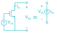
The circuit shown uses an NMOS transistor to implement a current source. For the transistor VTN = 1V and =12.5 uA/V2. The required value of VGS to get IDC = 25 μA and corresponding compliance voltage is:
Detailed Solution for Test: Electronic Devices - 5 - Question 7


2 = (VGS - 1)2‑
VGS = √2 + 1 = 2.414 V

To function as a current source, the transistor must be in saturation or VDS > VDS (sat).

VDS (sat) = VGS - VTN

= 2.414 – 1

= 1.414.

Hence compliance voltage = 1.414 V.
Compliance voltage is the minimum voltage required to achieve the desired performance.

*Answer can only contain numeric values
Test: Electronic Devices - 5 - Question 8

The output resistance R0 of the NMOS circuit if ID = 0.5 mA, λ = 0.02 V-1  _____ kilo ohms.


Detailed Solution for Test: Electronic Devices - 5 - Question 8

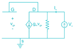
The small signal model with a test voltage Vx is shown.

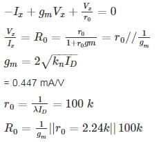
The output resistance is given by:
 

From the circuit, Vgs = Vx

Applying KCL:

Test: Electronic Devices - 5 - Question 9

For a MOSFET with gate plate area 0.5 × 10⁻² cm2 and oxide layer thickness 80 nm, the value of MOS capacitance and its break down voltage are: (assume relative di-electric constant of sio2, ϵr = 4 and ϵ0 = 8.854 × 10⁻¹⁴ F/cm and dielectric strength of sio2 film is 5 × 10⁶ V/cm)

Detailed Solution for Test: Electronic Devices - 5 - Question 9

Given gate plate area, which is also MOS capacitor area A = 0.5 × 10⁻²cm2

Oxide layer thickness tox = 80 nm

The value of MOS capacitance:
 

= 0.22 μF

Dielectric breakdown happens of field  greater than dielectric strength (5 × 10⁶ V/cm)

V = 5 × 108 × 80 × 10-9 V = 40V

*Answer can only contain numeric values
Test: Electronic Devices - 5 - Question 10

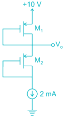
In the circuit shown in Figure, Transistors are characterized by  and λ = 0

The output voltage V0 is _______V


Detailed Solution for Test: Electronic Devices - 5 - Question 10

Gate is connected to drain Both Transistor are in Saturation.

For M1 Transistor:

⇒ (V - 8)2 = 4
⇒ V - 8 = ± 2

(i) Taking +ve, V = 8 + 2 = 10 V (Not Possible)
(ii) Taking -ve, V = 8 - 2 = 6 V

25 docs|263 tests
Information about Test: Electronic Devices - 5 Page
In this test you can find the Exam questions for Test: Electronic Devices - 5 solved & explained in the simplest way possible. Besides giving Questions and answers for Test: Electronic Devices - 5, EduRev gives you an ample number of Online tests for practice
Download as PDF