Electrical Engineering (EE) Exam  >  Electrical Engineering (EE) Tests  >  GATE Electrical Engineering (EE) Mock Test Series 2025  >  Test: Electrical & Electronic Measurements- 2 - Electrical Engineering (EE) MCQ

Test: Electrical & Electronic Measurements- 2 - Electrical Engineering (EE) MCQ


Test Description

10 Questions MCQ Test GATE Electrical Engineering (EE) Mock Test Series 2025 - Test: Electrical & Electronic Measurements- 2

Test: Electrical & Electronic Measurements- 2 for Electrical Engineering (EE) 2025 is part of GATE Electrical Engineering (EE) Mock Test Series 2025 preparation. The Test: Electrical & Electronic Measurements- 2 questions and answers have been prepared according to the Electrical Engineering (EE) exam syllabus.The Test: Electrical & Electronic Measurements- 2 MCQs are made for Electrical Engineering (EE) 2025 Exam. Find important definitions, questions, notes, meanings, examples, exercises, MCQs and online tests for Test: Electrical & Electronic Measurements- 2 below.
Solutions of Test: Electrical & Electronic Measurements- 2 questions in English are available as part of our GATE Electrical Engineering (EE) Mock Test Series 2025 for Electrical Engineering (EE) & Test: Electrical & Electronic Measurements- 2 solutions in Hindi for GATE Electrical Engineering (EE) Mock Test Series 2025 course. Download more important topics, notes, lectures and mock test series for Electrical Engineering (EE) Exam by signing up for free. Attempt Test: Electrical & Electronic Measurements- 2 | 10 questions in 30 minutes | Mock test for Electrical Engineering (EE) preparation | Free important questions MCQ to study GATE Electrical Engineering (EE) Mock Test Series 2025 for Electrical Engineering (EE) Exam | Download free PDF with solutions
Test: Electrical & Electronic Measurements- 2 - Question 1

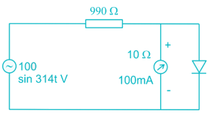
An ideal diode has been connected across a 10 Ω, 100 mA, center-zero PMMC meter as shown in figure.
The meter will read
Detailed Solution for Test: Electrical & Electronic Measurements- 2 - Question 1

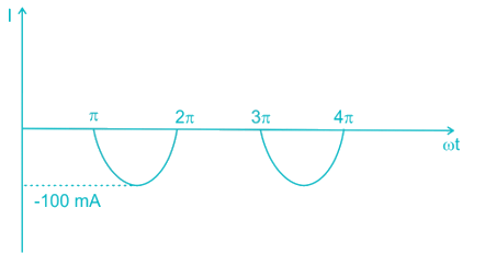
In positive half cycle, the diode gets forward biased. Hence diode is in on state so, no current will flows through ammeter.
In negative half cycle, the diode gets reverse biased. Hence diode is in off state. So, the current flows through ammeter.

The current waveform will be,

PMMC instrument measures average value.

*Answer can only contain numeric values
Test: Electrical & Electronic Measurements- 2 - Question 2

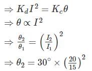
The deflecting torques of an ammeter varies as the square of the current passing through it. If a current of 15A produces a deflection of 30°, The deflection of a current of 20 A when instrument is spring controlled will be _____________ (in degrees).


Detailed Solution for Test: Electrical & Electronic Measurements- 2 - Question 2

Td = KdI2
for spring control Tc = Kcθ

Test: Electrical & Electronic Measurements- 2 - Question 3

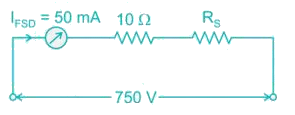
A moving iron instrument has 10 Ω resistance and gives full scale deflection when carrying 50 mA. It can be used measure 750 V by using what resistance?

Detailed Solution for Test: Electrical & Electronic Measurements- 2 - Question 3

Given that,
Full scale deflection = 50 mA
Internal resistance of instrument = 10 Ω
We can increase the range of voltage by using series resistance.

750 = (10 + RS) × 50 × 10-3
⇒ RS + 10 = 15,000
⇒ RS = 14990 Ω
Hence the resistance should be connected in series.

*Answer can only contain numeric values
Test: Electrical & Electronic Measurements- 2 - Question 4

What will be the reading (in V) when a voltage e = 200 sin ωt + 40 sin (3ωt + 30°) + 30 cos (5 ωt + 21.5°) v is applied to an electrodynamometer voltmeter.


Detailed Solution for Test: Electrical & Electronic Measurements- 2 - Question 4

Electrodynamometer voltmeter reads the rms value.
Given that,
e = 200 sin ωt + 40 sin (3ωt + 30°) + 30 cos (5 ωt + 21.5°) V

Test: Electrical & Electronic Measurements- 2 - Question 5

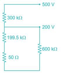
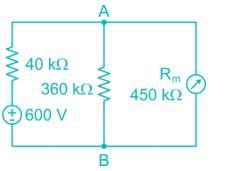
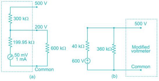
A 600 kΩ resistor is connected from the 200 V terminal to the common terminal of a dual scale voltmeter, as shown in figure (a). This modified voltmeter is then used to measure the voltage across the 360 kΩ resistor in the circuit in figure (b). What is the reading on the 500 V scale of the meter?
Detailed Solution for Test: Electrical & Electronic Measurements- 2 - Question 5

From the figure (a)
Internal resistance of galvanometer = 50 mV/1 mA
= 50 Ω
Now the circuit becomes,

Total internal resistance of voltmeter for 500 V scale,
Rm = 300 + [(199.5 + 0.05)||600]
= 300 + [200||600]
= 300 + 150 = 450 kΩ
Now, the voltmeter with internal resistance of 450 kΩ and 500 V scale is used to measure voltage in the circuit shown in fig (b).
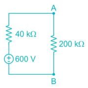
Now, the circuit becomes

Because of voltmeter resistance, the load resistance becomes = 360||450 = 200 kΩ

By voltage division,

*Answer can only contain numeric values
Test: Electrical & Electronic Measurements- 2 - Question 6

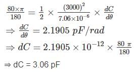
The spring constant of a 3000 V electrostatic voltmeter is 7.06 × 10⁻⁶ Nm/rad. The full scale deflection of the instrument is 80°. Assuming the rate of change of capacitance with angular deflection to be constant over the operating range. Calculate the total change of capacitance (in pF) from zero to full scale.


Detailed Solution for Test: Electrical & Electronic Measurements- 2 - Question 6

We know that,

Given that,

V = 3000 V
K = 7.06 × 10⁻⁶ Nm/rad

Test: Electrical & Electronic Measurements- 2 - Question 7

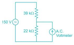
Two different a.c, voltmeters are used to measure the voltage across the 22 kΩ resister shown in figure. Meter A has a.c. sensitivity of 10 kΩ/V, a guaranteed accuracy of 98% at full scale, and is set on its 200V scale. Meter B has an a.c. sensitivity of 4kΩ/V. a guaranteed accuracy of 98.5% at full scale, and is set on its (0-100)V range. Which meter Provides more accurate results?
Detailed Solution for Test: Electrical & Electronic Measurements- 2 - Question 7

Sensitivity of meter A, SA = 10 kΩ/V
Full scale reading of meter A, VFSD(A) = 200 V
Internal resistance of meter A,
RV(A) = 10 kΩ/V × 200 V
= 2000 KΩ
Guaranteed accuracy of Meter A = 98% at FSD.
Error of meter 
Sensitivity of meter B, SB = 4KΩ/V
Full Scale reading of meter B, VFSD = 100V
Internal resistance of meter B,
RV(B) = 4 KΩ/V × 100 = 400 KΩ
Guaranteed accuracy of meter B = 98.5% at FSD
Error of meter 
True reading across 22 KΩ resister 
If we use meter A, then the reading will be the effective will be, The effective resistance across 22kΩ
= 22k ||2000k = 21.76 kΩ
Now the reading 
But the meter has an error of 4V
Hence the range of reading = [49.71, 57.71]
If we use meter B, then the reading will be
The effective resistance across 22kΩ,
= 22k||400k = 20.85kΩ
Now, the reading 
But the meter has an error of 1.5V
Hence, the range of reading = [50.75, 53.75]
By observing both the readings we can conclude that meter B provides accurate results.

*Answer can only contain numeric values
Test: Electrical & Electronic Measurements- 2 - Question 8

A moving iron instrument is calibrated with full scale deflection on 100 V DC. This instrument is used to measure 100 V at 50 Hz supply. Find the percentage error in reading if the instrument has a resistance of 2 kΩ and an inductance of 0.5 H


Detailed Solution for Test: Electrical & Electronic Measurements- 2 - Question 8

Full scale deflection of instrument (VFSD) = 100V
Resistance (Rm) = 2 kΩ
Inductance (Lm) = 0.5 H
XL = 2πfL = 2π × 50 × 0.5 = 157.08 Ω

Current through meter when 100 V at 50 Hz supply is applied

Voltage reading of meter 
 

*Answer can only contain numeric values
Test: Electrical & Electronic Measurements- 2 - Question 9

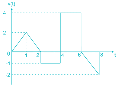
An input voltage represented by wave from as shown below is applied to a PMMC instrument. The reading of the instrument will be __ ( in V)

Detailed Solution for Test: Electrical & Electronic Measurements- 2 - Question 9

PMMC measures average value.
The average value

Test: Electrical & Electronic Measurements- 2 - Question 10

The coil of a moving coil voltmeter is 50 mm long and 40 mm wide and has 120 turns on it. The control spring exerts a torque 200 × 10-6 n – m when the deflection is 100 divisions on full scale. If the flux density of the magnetic field in the air gap is 1.2 wb/m2. The resistance that must be put in series with the coil to give one volt per division.

Detailed Solution for Test: Electrical & Electronic Measurements- 2 - Question 10

Tc = 200 × 10-6 N – m
Td = B I N A
= 1.2 × I × 120 × 50 × 40 × 10-6
= 288 × 10-3 I n – m
At equilibrium,
Tc = Td
⇒ 200 × 10-6 = 288 × 10-3 I
⇒ I = 0.694 mA.
Let the resistance of the voltmeter circuit be R voltage across the instrument = 0.694 × 10⁻³ R
This produces a deflection of 100 divisions.
Volts per division 
This value should be equal to 1 in order to get 1 volt per division.

25 docs|247 tests
Information about Test: Electrical & Electronic Measurements- 2 Page
In this test you can find the Exam questions for Test: Electrical & Electronic Measurements- 2 solved & explained in the simplest way possible. Besides giving Questions and answers for Test: Electrical & Electronic Measurements- 2, EduRev gives you an ample number of Online tests for practice
Download as PDF