Test: Logic Gates & Switching Circuits- 2


Test Description

20 Questions MCQ Test GATE Electrical Engineering (EE) 2023 Mock Test Series | Test: Logic Gates & Switching Circuits- 2

Test: Logic Gates & Switching Circuits- 2 for Electrical Engineering (EE) 2023 is part of GATE Electrical Engineering (EE) 2023 Mock Test Series preparation. The Test: Logic Gates & Switching Circuits- 2 questions and answers have been prepared according to the Electrical Engineering (EE) exam syllabus.The Test: Logic Gates & Switching Circuits- 2 MCQs are made for Electrical Engineering (EE) 2023 Exam. Find important definitions, questions, notes, meanings, examples, exercises, MCQs and online tests for Test: Logic Gates & Switching Circuits- 2 below.
Solutions of Test: Logic Gates & Switching Circuits- 2 questions in English are available as part of our GATE Electrical Engineering (EE) 2023 Mock Test Series for Electrical Engineering (EE) & Test: Logic Gates & Switching Circuits- 2 solutions in Hindi for GATE Electrical Engineering (EE) 2023 Mock Test Series course. Download more important topics, notes, lectures and mock test series for Electrical Engineering (EE) Exam by signing up for free. Attempt Test: Logic Gates & Switching Circuits- 2 | 20 questions in 60 minutes | Mock test for Electrical Engineering (EE) preparation | Free important questions MCQ to study GATE Electrical Engineering (EE) 2023 Mock Test Series for Electrical Engineering (EE) Exam | Download free PDF with solutions
1 Crore+ students have signed up on EduRev. Have you? Download the App
Test: Logic Gates & Switching Circuits- 2 - Question 1

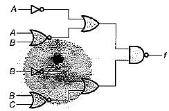
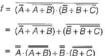
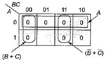
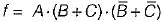
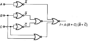
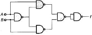
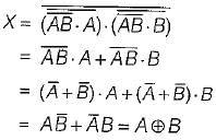
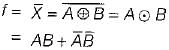
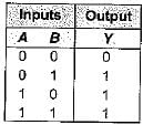
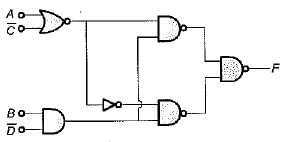
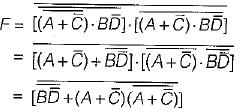
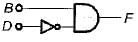
For the logic diagram shown below, the output f is

Detailed Solution for Test: Logic Gates & Switching Circuits- 2 - Question 1

From given logic diagram, output is:

= A.(A + B) + B.(B + C)
= A.A + A B + BB + BC
= A + AB + B + BC
= A(1 + B) + B(1 + C)
= A + B

Test: Logic Gates & Switching Circuits- 2 - Question 2

The minimum number of NOR gates requires to implement the expression
f(A, B, C) = πM(0, 1, 2, 3, 4, 7) is

Detailed Solution for Test: Logic Gates & Switching Circuits- 2 - Question 2

Given expressio n is f = πM( 0, 1, 2, 3, 4, 7)
The K-map for this expression is shown below.

The minimized expression in POS form is

The minimized expression 'f' can be implemented using two input NOR gate as shown below.

Thus, we require six NOR gates.

Test: Logic Gates & Switching Circuits- 2 - Question 3

Consider the following statements associated with logic gates:
1. An OR gate in the positive logic system becomes an AND gate in the negative logic system and vice-versa.
2. The dual of an expression is obtained by changing ANDs to ORs, ORs to ANDs.Os to 1s, to Os and by complementing the variables.
3. NAND and NOR are the only two available universal logic gates.
4. Universal gates do not follow commutative law
5. On logic diagrams, an inversion bubble at the point where the input is connected to a gate, indicates an active-HIGH input.
Which of the statements given above is/are not correct?

Detailed Solution for Test: Logic Gates & Switching Circuits- 2 - Question 3
  • Statement-1 is correct because positive and negative logics give rise to a basic duality in all Boolean identities. Here, an AND gate becomes an OR gate and an OR gate becomes an AND gate and vice-versa.
  • For obtaining dual expression, variables are not complemented. Hence, statement-2 is not correct.
  • NAND and NOR are the only two universal gates while NOT, OR, AND are three basic gates. Thus, statement-3 is correct.
  • Universal gates follow associate law but not commutative law. Hence, statement-4 is correct.
  • An inversion bubble on logic diagram at input indicates an active-LOW input. Thus, statement-5 is not correct.

Hence, statements 1 and 3 are correct while statements 2, 4 and 5 are false.

Test: Logic Gates & Switching Circuits- 2 - Question 4

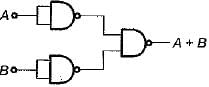
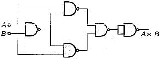
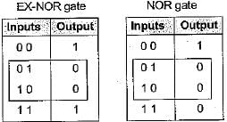
The number of two input NAND gate required to implement an OR gate and an EX-NOR gate are respectively

Detailed Solution for Test: Logic Gates & Switching Circuits- 2 - Question 4

OR gate using NAND gate:

EX-NOR gate using NAND gate:

Thus, we require 3 NAND gates for an OR gate while 5 NAND gates for an EX-NOR gate.

Test: Logic Gates & Switching Circuits- 2 - Question 5

Three set of simultaneous equations are given by
(i) 
(ii) AB = AC
(iii) 
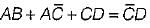
The solution of the above three set of simultaneous equations will be

Detailed Solution for Test: Logic Gates & Switching Circuits- 2 - Question 5

Given,

or,

i.e. must be 0 and B must be 0 Hence, A = 1 and B = 0
Also, AB = AC or 1.B - 1.C
or B = C
Hence, C = 0 (∵ B = 0)
Also,
or, 1.0 + 1.1 + 0.D = 1.D
or D = 1
Thus, the values of A, 6, Cand Dare given by
A = 1, B = 0, C = 0 and D = 1.

Test: Logic Gates & Switching Circuits- 2 - Question 6

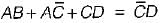
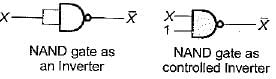
If one of the input to an EX-NOR gate is fixed to logic ‘1’, then output of this gate will be

Detailed Solution for Test: Logic Gates & Switching Circuits- 2 - Question 6


Output = X.1 +  = X = Input

Test: Logic Gates & Switching Circuits- 2 - Question 7

An AND gate

Detailed Solution for Test: Logic Gates & Switching Circuits- 2 - Question 7


The truth table for above circuit is shown below.

Hence, the output y is equivalent to output of an AND gate having two inputs A and 6. Thus, an AND gate is equivalent to a series switching circuit.

Test: Logic Gates & Switching Circuits- 2 - Question 8

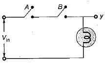
An XOR gate produces output 1 only when two inputs are

Detailed Solution for Test: Logic Gates & Switching Circuits- 2 - Question 8

For same inputs, A A = 0
For different inputs,

Test: Logic Gates & Switching Circuits- 2 - Question 9

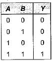
Consider the truth table shown beiow:

The logic gate represented by the above truth table is

Detailed Solution for Test: Logic Gates & Switching Circuits- 2 - Question 9

For same inputs, output (f) = 0
For different inputs, output (f) = 1
Hence, given truth table represents an EX-OR gate.

Test: Logic Gates & Switching Circuits- 2 - Question 10

A logic gate is an electronic circuit which

Test: Logic Gates & Switching Circuits- 2 - Question 11

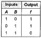
The output of a logic gate is ‘0’ when both its inputs are different. The gate is

Detailed Solution for Test: Logic Gates & Switching Circuits- 2 - Question 11

Truth tables

Thus, the gate can be either an EX-NOR or a NOR gate.

Test: Logic Gates & Switching Circuits- 2 - Question 12

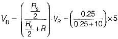
 For the diode circuit shown below, both the diodes D1, and Dare ideal.

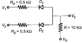
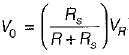
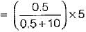
If VR= +5 V, then match List-I (Values of V1 and V2) with List-Il (Output voltage V0) and select the correct answer using the codes given below the lists:
List-I
V1 = 0 and V2 = 5 volt
V= V2 = 5 volt
V1 = V2 = 0 volt
List-ll
1 . 5 volt
2. 0.12 volt
3. 0.24 volt
4. 2.5 volt
Codes:
    A B C
(a) 3 1 2
(b) 4 1 3
(c) 2 3 4
(d) 3 4 2

Detailed Solution for Test: Logic Gates & Switching Circuits- 2 - Question 12
  • When V= 0 volt and V2 = 5 volt, diode D1 will be on.
    Using voltage division rule,


    = 0.24 volt
  • When V1 = V2 = 5 volt, then both diodes are off, no current flows anywhere, and V0 = 5 volt.
  • When V1 = V2 = 0 volt, then both diodes D1 and D2 will be on and their two Rs's will effectively come in parallel.

Thus,
= 0.12 V

Test: Logic Gates & Switching Circuits- 2 - Question 13

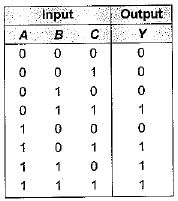
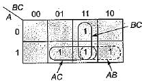
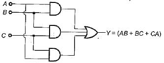
A circuit has three inputs and one output. The output is 1 if at least two of the three input variables are 1, otherwise it is zero. The minimum number of basic gates required to implement the output (Y) are

Detailed Solution for Test: Logic Gates & Switching Circuits- 2 - Question 13

The truth table for the given condition is shown below:

The K-map for above truth table is shown below.

Thus, Y = AB + BC + CA which can be implemented using 3 AND gates and 1 OR gate (total 4 basic gates).

Test: Logic Gates & Switching Circuits- 2 - Question 14

The boolean expression for the output f of the digital circuit shown below is

Detailed Solution for Test: Logic Gates & Switching Circuits- 2 - Question 14

Let the output of second last NAND gate be X. 
Then,

Thus, 

Given circuit represents EX-NOR gate using NAND gate

Test: Logic Gates & Switching Circuits- 2 - Question 15

In the truth table of an N-input OR gate, in the column for the output of the gate,

Detailed Solution for Test: Logic Gates & Switching Circuits- 2 - Question 15

A two input OR gate truth table is shown below:

From the truth table of OR gate it is clear tha output is 0’s only when all the inputs are 0’s otherwise for all other input combination outpu is always 1's. Hence, in the column for the outpu of the OR gate, the number of zeros is always 1's.

Test: Logic Gates & Switching Circuits- 2 - Question 16

 Consider the following statements associated with logic gates:
1. Logic circuit of any complexity can be realised by using only the three basic gates namely AND, GR and NOT.
2. AND, OR and NOT .gates are called universal building blocks.
3. AND/OR/INVERT logic (AO! logic) can be converted to NAND logic or NOR logic.
4. A NAND gate can be used as an inverter by connecting all its input terminals except one, to logic 1 and applying the signal to be inverted to the remaining terminal.
Q. Which of the statements given above is/are correct?

Detailed Solution for Test: Logic Gates & Switching Circuits- 2 - Question 16
  • Statement-1 is correct because any circuit can be realized using AND, OR and NOT gates.
  • The two logic gates NAND and NOR can realize any logic circuit single-handedly. Hence, these two gates are called universal building blocks. AND, OR and NOT are called basic gates. Thus, statement-2 is not correct.
  • Both NAND and NOR gates can perform all the three basic logic functions (AND, OR and NOT). Therefore, AND/OR/INVERT logic can be converted to NAND logic or NOR logic. Hence, statement-3 is correct.

  • Statement-4 is not correct.
Test: Logic Gates & Switching Circuits- 2 - Question 17

Assertion (A): When a number of variables are to be X-NORed, a number of two-input X-NOR gates can be used.
Reason (R): Three or more variable X-NOR gates will make the circuit costly.

Detailed Solution for Test: Logic Gates & Switching Circuits- 2 - Question 17

Since three or more variable X-NOR gates do not exist, therefore when a number of variables are to be X-NORed, a number of two input X-NOR gases have to be used. Thus, reason is not a correct statement.

Test: Logic Gates & Switching Circuits- 2 - Question 18

If 
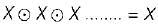
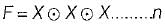
times, then the value of F is

Detailed Solution for Test: Logic Gates & Switching Circuits- 2 - Question 18

When n is even, 
When n is odd, 

Test: Logic Gates & Switching Circuits- 2 - Question 19

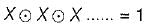
The simplified version of the logic circuit shown below consists of

Detailed Solution for Test: Logic Gates & Switching Circuits- 2 - Question 19

From the given circuit, output is
(∴ (X + Y) (X + Z) = X + YZ)


Therefore, the given logic circuit can be simplified as Do shown below.

Thus, it require a AND gate and a NOT gate.

Test: Logic Gates & Switching Circuits- 2 - Question 20

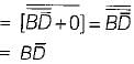
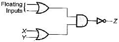
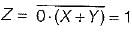
The circuit shown in figure is a ECL OR-AND- INVERTER circuit. The output Z is

Detailed Solution for Test: Logic Gates & Switching Circuits- 2 - Question 20

In case of ECL circuit, the floating inputs are considered as logic ‘0’. Hence output

22 docs|274 tests
Information about Test: Logic Gates & Switching Circuits- 2 Page
In this test you can find the Exam questions for Test: Logic Gates & Switching Circuits- 2 solved & explained in the simplest way possible. Besides giving Questions and answers for Test: Logic Gates & Switching Circuits- 2, EduRev gives you an ample number of Online tests for practice
Download as PDF

Download free EduRev App

Track your progress, build streaks, highlight & save important lessons and more!
(Scan QR code)