Test: Signal Flow Graphs - 1 - Electronics and Communication Engineering (ECE) MCQ
15 Questions MCQ Test GATE ECE (Electronics) Mock Test Series 2025 - Test: Signal Flow Graphs - 1

A signal flow graph is the graphical representation of the relationships between the variables of set linear algebraic equations.

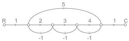
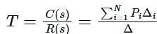
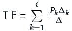
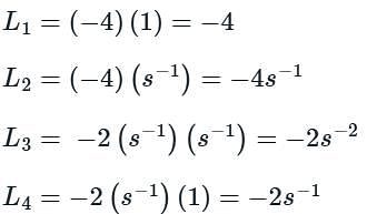
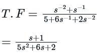
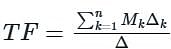
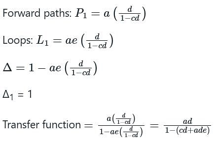
Use mason’s gain formula to find the transfer function of the given signal flow graph: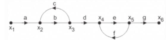
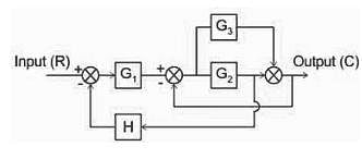
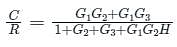
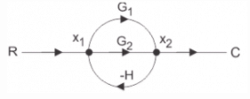
What will be the transfer function of the given block diagram?

Signal flow graphs are reliable to find transfer function than block diagram reduction technique.
Loop which do not possess any common node are said to be ___________ loops.
The relationship between an input and output variable of a signal flow graph is given by the net gain between the input and output node is known as the overall______________
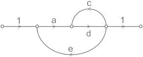
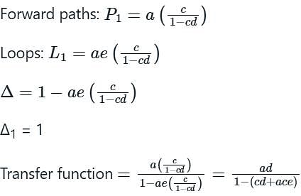
Use mason’s gain formula to calculate the transfer function of given figure:
Use mason’s gain formula to find the transfer function of the given figure:
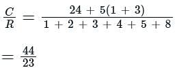
In the signal flow graph of figure given below, the gain C/R will be
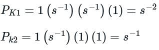
The signal flow graph for a system is given below.
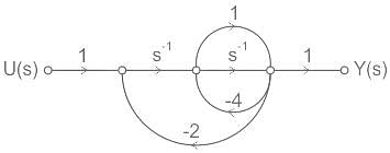
The transfer function Y(s)/U(s) for this system is
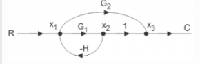
Which of the options is an equivalent representation of the signal flow graph shown here?


|
25 docs|263 tests
|


Important Questions for Signal Flow Graphs - 1
Signal Flow Graphs - 1 MCQs with Answers
Online Tests for Signal Flow Graphs - 1 GATE ECE (Electronics) Mock Test Series 2025
|
© EduRev
|
Education Revolution
|


|


