Test: Synchronous Machine of Electrical Machines - Electrical Engineering (EE) MCQ
10 Questions MCQ Test - Test: Synchronous Machine of Electrical Machines

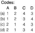
Match List-I (Name of test) with List-II (Result) and select the correct code given below the lists:
List-I
A. Open Circuit and short circuit test
B. Open circuit and zero power factor test
C. Slip test
D. Maximum lagging current test
List-II
1. Leakage reactance
2. Direct axis synchronous reactance
3. Quadrature axis synchronous reactance
4. Ratio of direct axis synchronous reactance to quadrature axis synchronous reactance
The phasor diagram of a synchronous machine connected to an infinite bus is shown below. The machine is acting as a
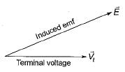
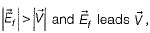 therefore machine is acting as a generator and operating at lagging Pf.
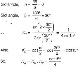
A 6-pole alternator with 36 slots carries a 3-phase distributed winding. Each coil is short-pitched by one slot. The winding factor is given by

A winding is distributed in the slots along the air-gap periphery
1. to add mechanical strength to the winding.
2. to reduce the amount of conductor material required.
3. to reduce the harmonics in the generated emf.
4. to reduce the size of the machine.
5. for full utilization of iron and conductor materials.
From these, the correct answer is
Which of the following graphs represents the speed-torque characteristic of a synchronous motor?
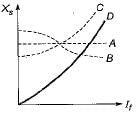
In figure the characteristic that corresponds to the variation of synchronous reactances of synchronous machine with the field current is
The four methods of calculating voltage regulation of a 3-phase alternator are:
1. Emf method
2. Saturated synchronous reactance method
3. New ASA method
4. Mmf method
The correct sequence in the ascending order of the values of regulation obtained by these methods is
The flux per pole in a synchronous motor with the field circuit ON and the stator disconnected from the supply is found to be 25 mWb. When the stator is connected to the rated supply with the field excitation unchanged, the flux per pole in the machine is found to be 20 mWb while the motor is running on no-load. Assuming no-load losses to be zero, the no-load current drawn by the motor from the supply
Which of the following method would give a lower than actual value of regulation of an alternator?
A synchronous motor is operating on no-load at unity power factor. If the field current is increased, the pf will become


Important Questions for Synchronous Machine of Electrical Machines
Synchronous Machine of Electrical Machines MCQs with Answers
Online Tests for Synchronous Machine of Electrical Machines
|
© EduRev
|
Education Revolution
|


|


