Test: Transient Response of DC & AC Networks - 1 - Electrical Engineering (EE) MCQ
10 Questions MCQ Test - Test: Transient Response of DC & AC Networks - 1
The natural response of an RLC circuit is described by the differential equation

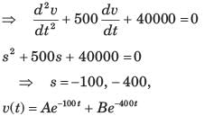
The v(t) is

The v(t) is
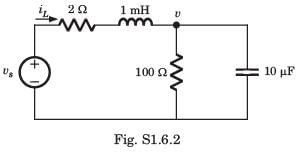
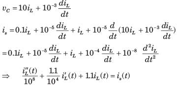
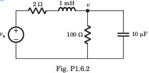
The differential equation for the circuit shown in fig. P1.6.2. is

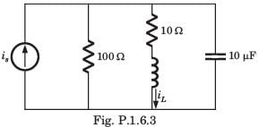
The differential equation for the circuit shown in fig. P1.6.3 is

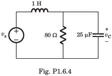
In the circuit of fig. P.1.6.4 vs = 0 for t > 0. The initial condition are v(0) = 6 V and dv(0) dt = -3000 Vs. The v(t) for t > 0 is
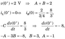
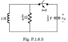
The circuit shown in fig. P1.6.5 has been open for a long time before closing at t = 0. The initial condition is v(0) = 2 V. The v(t) for t > is
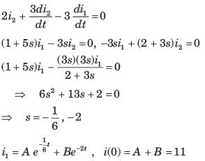
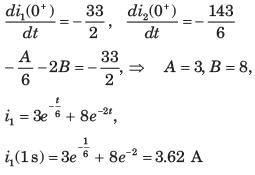
Circuit is shown in fig. P.1.6. Initial conditions are i1(0) = i2(0) = 11A
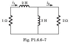
Q. i1 (1 s) = ?
Circuit is shown in fig. P.1.6. Initial conditions are i1(0) = i2(0) = 11A
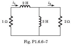
Q. i2 (1 s) = ?
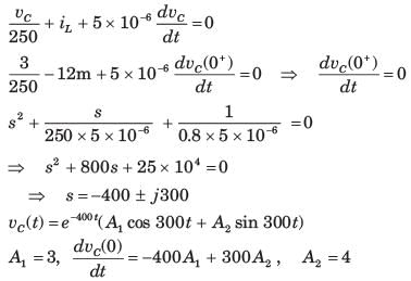
The circuit shown in fig. P1.6.9 is in steady state with switch open. At t = 0 the switch is closed. The output voltage vC(t) for t > 0 is
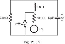
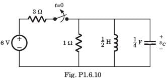
The switch of the circuit shown in fig. P1.6.10 is opened at t = 0 after long time. The v(t) , for t > 0 is
