Electrical Engineering (EE) Exam  >  Electrical Engineering (EE) Tests  >  GATE Electrical Engineering (EE) Mock Test Series 2025  >  Test: Diode Rectifiers - Electrical Engineering (EE) MCQ

Test: Diode Rectifiers - Electrical Engineering (EE) MCQ


Test Description

10 Questions MCQ Test GATE Electrical Engineering (EE) Mock Test Series 2025 - Test: Diode Rectifiers

Test: Diode Rectifiers for Electrical Engineering (EE) 2025 is part of GATE Electrical Engineering (EE) Mock Test Series 2025 preparation. The Test: Diode Rectifiers questions and answers have been prepared according to the Electrical Engineering (EE) exam syllabus.The Test: Diode Rectifiers MCQs are made for Electrical Engineering (EE) 2025 Exam. Find important definitions, questions, notes, meanings, examples, exercises, MCQs and online tests for Test: Diode Rectifiers below.
Solutions of Test: Diode Rectifiers questions in English are available as part of our GATE Electrical Engineering (EE) Mock Test Series 2025 for Electrical Engineering (EE) & Test: Diode Rectifiers solutions in Hindi for GATE Electrical Engineering (EE) Mock Test Series 2025 course. Download more important topics, notes, lectures and mock test series for Electrical Engineering (EE) Exam by signing up for free. Attempt Test: Diode Rectifiers | 10 questions in 30 minutes | Mock test for Electrical Engineering (EE) preparation | Free important questions MCQ to study GATE Electrical Engineering (EE) Mock Test Series 2025 for Electrical Engineering (EE) Exam | Download free PDF with solutions
Test: Diode Rectifiers - Question 1

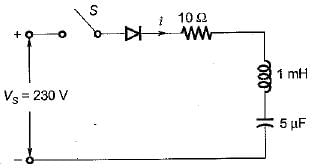
The circuit shown below is initially relaxed. With switch closed at t = 0, the conduction time of diode is around
Detailed Solution for Test: Diode Rectifiers - Question 1

For the series RLC diode circuit, the current i(t) is given by

Here 

The diode will stop conducting when ωr t1 = π.
∴ Conduction time of diode,

Test: Diode Rectifiers - Question 2

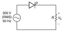
In the phase-controlled half-wave converter shown above, the thyristor is fired in every positive half cycle of the input voltage, at an angle α. The firing angle for the peak value of the instantaneous output voltage of 200 V would be close to
Detailed Solution for Test: Diode Rectifiers - Question 2

For α < 90° Vm = Vp
 For α > 90° Vm sinα = Vp
VRMS = 200 V
⇒ Vm = 200 √2
200 √2 sin α = 200

α = 45°
α = 90 + 45 = 135°

Test: Diode Rectifiers - Question 3

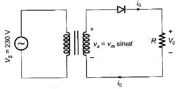
A single-phase 230 V, 1 kW heater is connected across single-phase 230 V, 50 Hz supply through a diode as shown in figure. The power delivered to the heater element is
Detailed Solution for Test: Diode Rectifiers - Question 3

The rms value of output voltage is:


Heater resistance

∴ Power absorbed by heater element

Test: Diode Rectifiers - Question 4

A single-phase full-bridge diode rectifier delivers a load current of 10 A, which is ripple free. The rms and average values of diode currents are respectively

Detailed Solution for Test: Diode Rectifiers - Question 4

Given, I0 = 10A
The rms value of diode current,

The average value of diode current,

Test: Diode Rectifiers - Question 5

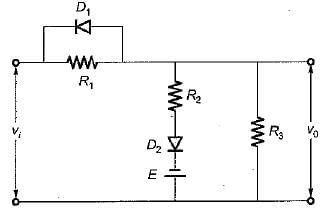
In the circuit shown below, the diode states at the extremely large negative value of the input voltage vi are
Detailed Solution for Test: Diode Rectifiers - Question 5

If vi is of very large negative value Ivi| > |E|, then diode D1 will be forward biased (ON) while diode D2 will be reverse biased (OFF).

Test: Diode Rectifiers - Question 6

A single-phase full-bridge diode rectifier delivers a constant load current of 20 A. The rms and average values of source current are respectively

Detailed Solution for Test: Diode Rectifiers - Question 6
  • The full-bridge rectifier delivers a constant load current of 20 A, which alternates in direction through the source, forming a pulsating AC waveform.
  • For this waveform:
    • RMS value: Equal to the load current, Irms=20 A.
    • Average value: Calculated from the magnitude, Iavg=20 A.
  • Both RMS and average values match because the current magnitude remains constant.
  • Correct answer: (a) 20 A, 20 A.
Test: Diode Rectifiers - Question 7

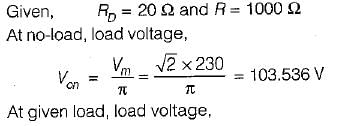
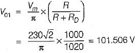
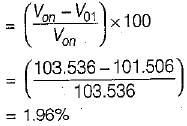
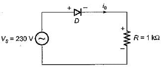
A diode whose internal resistance is 20 Q is to supply power to a 1 kΩ load from a 230 V (rms) source of supply as shown in figure below. The percentage regulation from no load to the given load is
Detailed Solution for Test: Diode Rectifiers - Question 7


∴ Voltage regulation

Test: Diode Rectifiers - Question 8

Assertion (A): A single-phase half-wave rectifier circuit is popularly known as one-pulse rectifier.
Reason (R) : A single-phase half-wave rectifier circuit is used to convert ac power to dc.

Detailed Solution for Test: Diode Rectifiers - Question 8

A single-phase half-wave rectifier is popularly known as one-pulse converter because for one cycle of supply voltage, there is one half-cycle of output, or load voltage. Hence, both assertion and reason are true but reason is not the correct explanation of assertion.

Test: Diode Rectifiers - Question 9

Assertion (A) : In 3-phase converters, the ripple frequency of the converter output voltage is higher than in single phase converter.
Reason (R) : The load current is mostly discontinuous in 3-phase converters.

Detailed Solution for Test: Diode Rectifiers - Question 9

The load current is mostly continuous in 3-phase converters. Hence reason is a false statement.

Test: Diode Rectifiers - Question 10

Assertion (A) : In a half-wave rectifier with R-L load and with freewheeling diode, the input Volt- Ampere demand is less.
Reason (R) : With freewheeling diode, the stored energy is in the load itself.

25 docs|247 tests
Information about Test: Diode Rectifiers Page
In this test you can find the Exam questions for Test: Diode Rectifiers solved & explained in the simplest way possible. Besides giving Questions and answers for Test: Diode Rectifiers, EduRev gives you an ample number of Online tests for practice
Download as PDF