Electrical Engineering (EE) Exam  >  Electrical Engineering (EE) Tests  >  GATE Electrical Engineering (EE) Mock Test Series 2025  >  Test: Power Electronics - 2 - Electrical Engineering (EE) MCQ

Test: Power Electronics - 2 - Electrical Engineering (EE) MCQ


Test Description

10 Questions MCQ Test GATE Electrical Engineering (EE) Mock Test Series 2025 - Test: Power Electronics - 2

Test: Power Electronics - 2 for Electrical Engineering (EE) 2025 is part of GATE Electrical Engineering (EE) Mock Test Series 2025 preparation. The Test: Power Electronics - 2 questions and answers have been prepared according to the Electrical Engineering (EE) exam syllabus.The Test: Power Electronics - 2 MCQs are made for Electrical Engineering (EE) 2025 Exam. Find important definitions, questions, notes, meanings, examples, exercises, MCQs and online tests for Test: Power Electronics - 2 below.
Solutions of Test: Power Electronics - 2 questions in English are available as part of our GATE Electrical Engineering (EE) Mock Test Series 2025 for Electrical Engineering (EE) & Test: Power Electronics - 2 solutions in Hindi for GATE Electrical Engineering (EE) Mock Test Series 2025 course. Download more important topics, notes, lectures and mock test series for Electrical Engineering (EE) Exam by signing up for free. Attempt Test: Power Electronics - 2 | 10 questions in 30 minutes | Mock test for Electrical Engineering (EE) preparation | Free important questions MCQ to study GATE Electrical Engineering (EE) Mock Test Series 2025 for Electrical Engineering (EE) Exam | Download free PDF with solutions
Test: Power Electronics - 2 - Question 1

In a thyristor

Detailed Solution for Test: Power Electronics - 2 - Question 1

Latching current is the minimum value of anode current which it must attain during turn – ON process to maintain conduction when gate signal is removed.

Holding current is the minimum value of anode current below which it must fall for turning – OFF the thyristor.

Test: Power Electronics - 2 - Question 2

Read the given statements below regarding turning – on an SCR with a gate signal.

(1)  An SCR must be forward – biased.

(2)  Gate pulse width must be less than the turn-on time of an SCR.

(3)  Anode to cathode voltage must be more than finger voltage.

(4)  The magnitude of gate current must be less than the minimum gate current required to turn – on a thyristor.

(5)  The magnitude of gate current must be less than the maximum gate current allowed 

Which of the above statements are false.

Detailed Solution for Test: Power Electronics - 2 - Question 2

1. Anode must be positive with respect to cathode.

2.  Gate pulse must be more than the turn – on time of an SCR. This will ensure that anode current exceeds the latching current before gate signal is removed.

3.  A finger voltage is that voltage below which an SCR cannot be turned on with a gate signal.

4.  Magnitude of gate current must be more than the minimum gate current required to turn – on a thyristor.

Test: Power Electronics - 2 - Question 3

An SCR is rated for 700 V PIV. What is the value for which the device can be operated if the voltage safety is 2.

Detailed Solution for Test: Power Electronics - 2 - Question 3

P.I.V = Vm × Voltage safety factor

700 = Vm × 2

Vm = 350 V

Test: Power Electronics - 2 - Question 4

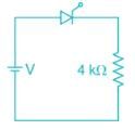
What should be the input voltage to turn off the SCR in the circuit shown in figure below when holding current of the SCR is 4 mA and load resistance is 4 kΩ.
Detailed Solution for Test: Power Electronics - 2 - Question 4

To turn off the SCR anode current should go less than holding current

⇒ V = 4 × 10-3 × 4 × 103

⇒ V = 16 V

Form the options, V = 15 V is correct. for the remaining options, holding current is less than anode current.

Test: Power Electronics - 2 - Question 5

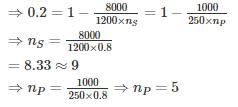
SCR with a rating of 1200 V and 250 A are available to be used in a string to handle 8 kV and 1kA. The number of parallel and series units required are respectively _____ (Take derating factor is 0.2)

Detailed Solution for Test: Power Electronics - 2 - Question 5

Derating factor = 1 – string efficiency

Test: Power Electronics - 2 - Question 6

An SCR has half cycle source current rating of 3000 A for 50 Hz supply. It’s one cycle surge current and I2t rating respectively are

Detailed Solution for Test: Power Electronics - 2 - Question 6

Let I and Isb be the one – cycle and sub – cycle surge current ratings of the SCR respectively

t = 10 ms, T = 20 ms

⇒ I = 2121.32 A

I2t rating = I2 × 1/2f

= 45,000 Amp2.sec

*Answer can only contain numeric values
Test: Power Electronics - 2 - Question 7

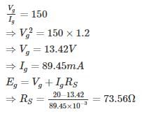
For an SCR, the gate – cathode characteristic has a straight line slope of 150. For trigger source voltage of 20 V and allowable gate power dissipation of 1.2 watts, the gate – source resistance is _______ (in Ω)


Detailed Solution for Test: Power Electronics - 2 - Question 7

VgIg = 1.2 W

*Answer can only contain numeric values
Test: Power Electronics - 2 - Question 8

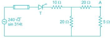
Thyristor shown in figure below has I2t rating of 60 A2s. If terminal A gets short circuited to ground, calculate the fault clearance time so that SCR ins not damaged – (in ms)

Detailed Solution for Test: Power Electronics - 2 - Question 8

Maximum fault current occurs when source voltage is at its peak = 240 √2 V

When terminal ‘A’ gets short – circuited to ground the resistance offered to the source

= 10+(20||20) = 20 Ω

⇒ tc = 208.33 ms

*Answer can only contain numeric values
Test: Power Electronics - 2 - Question 9

It is required to operate 200 A SCR in parallel with 300 A SCR with their respective ON – State voltage drop of 2 V and 1.2 V. calculate the value of resistance to be inserted in series with each SCR so that they share the total load of 500 A in proportional to their current ratings – (in mΩ)


Detailed Solution for Test: Power Electronics - 2 - Question 9

Dynamic resistance of SCR with 200 A

= 2/200 = 0.01Ω = 10 mΩ
Dynamic resistance of SCR with 300 A


= 1.2/300 = 0.004Ω = 4 mΩ
Let Rs be the resistance inserted in series with each SCR.

Current shared by SCR= 500 
Current shared by SCR= 500  

⇒ 12 + 3 Rs = 20 + 2Rs

⇒ Rs = 8 m Ω

Test: Power Electronics - 2 - Question 10

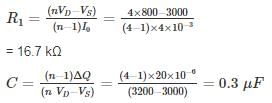
Four 800 V thyristors are connected in series to share 3 kV supply voltage. The maximum forward leakage current is 4 mA, and the maximum difference in recovery charge is 20 μC.
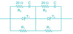
Determine the value of R1 and C (assuming equal voltage sharing).

Detailed Solution for Test: Power Electronics - 2 - Question 10

Here, n = 4

25 docs|247 tests
Information about Test: Power Electronics - 2 Page
In this test you can find the Exam questions for Test: Power Electronics - 2 solved & explained in the simplest way possible. Besides giving Questions and answers for Test: Power Electronics - 2, EduRev gives you an ample number of Online tests for practice
Download as PDF