Electrical Engineering (EE) Exam  >  Electrical Engineering (EE) Tests  >  GATE Electrical Engineering (EE) Mock Test Series 2025  >  Test: Thyristor Commutation Techniques - Electrical Engineering (EE) MCQ

Test: Thyristor Commutation Techniques - Electrical Engineering (EE) MCQ


Test Description

10 Questions MCQ Test GATE Electrical Engineering (EE) Mock Test Series 2025 - Test: Thyristor Commutation Techniques

Test: Thyristor Commutation Techniques for Electrical Engineering (EE) 2025 is part of GATE Electrical Engineering (EE) Mock Test Series 2025 preparation. The Test: Thyristor Commutation Techniques questions and answers have been prepared according to the Electrical Engineering (EE) exam syllabus.The Test: Thyristor Commutation Techniques MCQs are made for Electrical Engineering (EE) 2025 Exam. Find important definitions, questions, notes, meanings, examples, exercises, MCQs and online tests for Test: Thyristor Commutation Techniques below.
Solutions of Test: Thyristor Commutation Techniques questions in English are available as part of our GATE Electrical Engineering (EE) Mock Test Series 2025 for Electrical Engineering (EE) & Test: Thyristor Commutation Techniques solutions in Hindi for GATE Electrical Engineering (EE) Mock Test Series 2025 course. Download more important topics, notes, lectures and mock test series for Electrical Engineering (EE) Exam by signing up for free. Attempt Test: Thyristor Commutation Techniques | 10 questions in 30 minutes | Mock test for Electrical Engineering (EE) preparation | Free important questions MCQ to study GATE Electrical Engineering (EE) Mock Test Series 2025 for Electrical Engineering (EE) Exam | Download free PDF with solutions
Test: Thyristor Commutation Techniques - Question 1

To turn-off or commutate a thyristor

Detailed Solution for Test: Thyristor Commutation Techniques - Question 1

To turn-off a thyristor, anode current must be reduced below holding current and a reverse bias must be applied across thyristor for a finite period of time. If all these two conditions are not met simultaneously then forced commutation can be used to turn-off the thyristor.

Test: Thyristor Commutation Techniques - Question 2

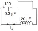
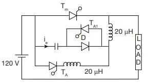
A commutation circuit shown in figure

What will be the maximum possible value of current through auxiliary thyristor
TA when C = 0.3 mF L = 20 μH
Detailed Solution for Test: Thyristor Commutation Techniques - Question 2


The maximum value of capacitor voltage is Vc = 120 V after long time when TA, TA1 is ON

Then the maximum value of current Ic max

Test: Thyristor Commutation Techniques - Question 3

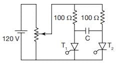
A voltage commutation circuit shown in figure. If turn off time of SCR is 10 μs and safety margin of 1.5. What will be the minimum value of capacitor required for commutation.
Detailed Solution for Test: Thyristor Commutation Techniques - Question 3

The circuit turn off time for thyristors are
t c1 = R1 C ln 2
t c2 = R2 C ln 2
t c1 = t c2
R1 = R2
safety margin = 1.5
for safe turn off
R1 c ln 2 = 1.5 t c1
t c1 = 10 m sec

Test: Thyristor Commutation Techniques - Question 4

Turn-on time (ton) of an SCR is related to its turn-off time (toff) in which of the following way?

Detailed Solution for Test: Thyristor Commutation Techniques - Question 4

The turn-on time of an SCR depends on time constant (L/R) of the load.

Test: Thyristor Commutation Techniques - Question 5

Assertion (A) : It is necessary to keep the thyristor reverse biased for a finite period before a forward anode voltage can be reapplied.
Reason (R) : Once the SCR starts conducting an appreciable forward current, the gate has no control on it and the device can be brought back to the blocking state only by reducing the forward current level below that of the holding current.

Detailed Solution for Test: Thyristor Commutation Techniques - Question 5

It is necessary to keep the thyristor reverse biased for a finite period before a forward anode voltage can be reapplied because if a forward voltage is applied immediately after reducing the anode current to zero, it will not block the forward voltage and will start conducting again, although it is not triggered by a gate pulse. Reason is also a true statement but not the correct explanation of assertion.

Test: Thyristor Commutation Techniques - Question 6

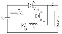
In a class D commutation as, shown in figure. L = 1 μH & C = 2 μF. For a constant load current of 100 A, calculate circuit turn off time for auxiliary thyristor
Detailed Solution for Test: Thyristor Commutation Techniques - Question 6

In class D commutation turn off time for auxillary thyristor is 

tc1 = 2.221 μs

Test: Thyristor Commutation Techniques - Question 7

Consider the following statements associated with various commutation techniques of a thyristor:
1. In forced commutation, the commutating components L and C carry load current continuously.
2. Forced commutation is usually employed in dc choppers.
3. In load commutation, L and Care connected in parallel with the load or C in series with the load.
4. Load commutation is employed in series inverters.
5. In class-C commutation, the main thyristor that is to be commutated is connected in parallel with the load.

Which of the statements given above are correct?

Detailed Solution for Test: Thyristor Commutation Techniques - Question 7
  • In forced commutation, the commutating components L and C do not carry load current continuously.
  • Forced commutation is usually employed in dc choppers because natural current zero is not available in the circuits containing dc choppers.
  • In load commutation. L and Care connected in series with the load or C in parallel with the load such that overall load circuit is underdamped.
  • Load commutation is employed in series inverters.
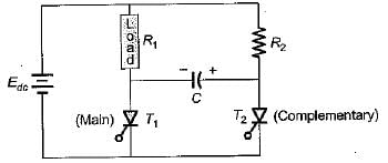
  •  In class-C commutation, the main thyristor that is to be commutated is connected in series with the load while the complementary thyristor is connected in parallel with the main thyristor as shown below.

Thus, statements 2 and 4 are only correct.

Test: Thyristor Commutation Techniques - Question 8

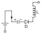
For the class-B commutation circuit shown below, the initial voltage across capacitor is 230 volt. For a constant load current of 300 A, the conduction time for the auxiliary thyristor is approximately equal to
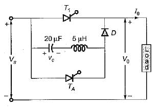
Detailed Solution for Test: Thyristor Commutation Techniques - Question 8

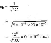
Given, L = 5μH, C = 20μF
Resonant frequency,

∴ Conduction time for auxiliary thyristor

Test: Thyristor Commutation Techniques - Question 9

For the circuit shown below, the peak value of the current through thyristors T1 and T2 are
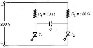
Detailed Solution for Test: Thyristor Commutation Techniques - Question 9

Given, Vs = 200 V, R= 10 Ω, and R2 = 100 Ω
Given circuit represents a class-C commutation circuit.
The peak value of current through thyristor T1 is


The peak value of current through thyristor T2 is

Test: Thyristor Commutation Techniques - Question 10

The SCR in the circuit shown below is forced commutated by a circuitry not shown in the figure. The SCR has minimum charging current of 5 mA to turn it on and its junction capacitance is 25 pF.
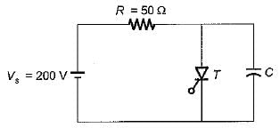
Detailed Solution for Test: Thyristor Commutation Techniques - Question 10

Under steady-state condition, voltage across capacitor is Vs = 200 V and SCR conducts having a current through it equal to

When the SCR is forced commutated, the capacitor voltage at time t is


 ...(i)
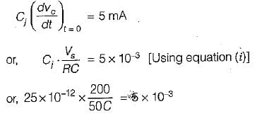
Let Cj be the junction capacitance of SCR. Now, when SCR get turned-on, the

or, 
= 0.02 μF
Thus, the minimum value of C so that SCR does not get turn-on is 0.02 μF.
If C > 0.02 μF, SCR will be turn-on.

25 docs|247 tests
Information about Test: Thyristor Commutation Techniques Page
In this test you can find the Exam questions for Test: Thyristor Commutation Techniques solved & explained in the simplest way possible. Besides giving Questions and answers for Test: Thyristor Commutation Techniques, EduRev gives you an ample number of Online tests for practice
Download as PDF