Civil Engineering (CE) Exam  >  Civil Engineering (CE) Tests  >  Topicwise Question Bank for Civil Engineering  >  Test: ILD & Rolling Loads - 3 - Civil Engineering (CE) MCQ

Test: ILD & Rolling Loads - 3 - Civil Engineering (CE) MCQ


Test Description

10 Questions MCQ Test Topicwise Question Bank for Civil Engineering - Test: ILD & Rolling Loads - 3

Test: ILD & Rolling Loads - 3 for Civil Engineering (CE) 2025 is part of Topicwise Question Bank for Civil Engineering preparation. The Test: ILD & Rolling Loads - 3 questions and answers have been prepared according to the Civil Engineering (CE) exam syllabus.The Test: ILD & Rolling Loads - 3 MCQs are made for Civil Engineering (CE) 2025 Exam. Find important definitions, questions, notes, meanings, examples, exercises, MCQs and online tests for Test: ILD & Rolling Loads - 3 below.
Solutions of Test: ILD & Rolling Loads - 3 questions in English are available as part of our Topicwise Question Bank for Civil Engineering for Civil Engineering (CE) & Test: ILD & Rolling Loads - 3 solutions in Hindi for Topicwise Question Bank for Civil Engineering course. Download more important topics, notes, lectures and mock test series for Civil Engineering (CE) Exam by signing up for free. Attempt Test: ILD & Rolling Loads - 3 | 10 questions in 30 minutes | Mock test for Civil Engineering (CE) preparation | Free important questions MCQ to study Topicwise Question Bank for Civil Engineering for Civil Engineering (CE) Exam | Download free PDF with solutions
Test: ILD & Rolling Loads - 3 - Question 1

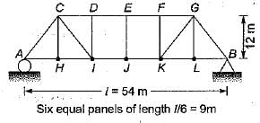
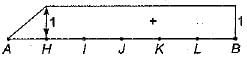
For the pin-joined plane truss shown in the below figure, which of the following diagrams represents the influence line for the bar force in the member CH?

+ sign indicates tension
- sign indicates compression

Detailed Solution for Test: ILD & Rolling Loads - 3 - Question 1

To determine the influence line for the bar force in the member CH of the pin-joined plane truss, we need to consider the effects of a moving load on the structure. The influence line shows how the internal force in a member varies as a point load moves across the truss.

  • The influence line for CH will peak when the load is directly over the member.
  • As the load moves away from CH, the internal force will decrease.
  • The shape of the influence line typically resembles a triangular or trapezoidal form depending on the geometry of the truss.
  • In this case, the correct diagram will show a positive value when the load is over CH, indicating tension, and a negative value when the load is further away, indicating compression.

By analysing the diagrams provided, option B correctly represents the influence line for member CH.

Test: ILD & Rolling Loads - 3 - Question 2

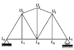
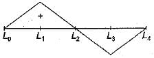
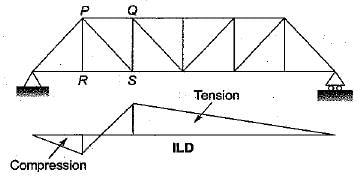
Which one of the following is the influence line for the force in the member U1L2 of the plane pin-jointed frame shown in the figure given below?

Detailed Solution for Test: ILD & Rolling Loads - 3 - Question 2

The influence line for the force in member U1L2 of the given frame can be determined by analysing how the applied loads affect that specific member. To find this, follow these steps:

  • Identify the location of member U1L2 within the frame.
  • Consider moving a unit load across the entire span of the frame.
  • At each position of the load, calculate the force in member U1L2.
  • Plot these forces against the position of the load to create the influence line.

In this case, the correct influence line will show how the force in U1L2 varies with the position of the unit load. The line will typically peak where the load has the greatest effect on the member.

Based on this analysis, option B correctly represents the influence line for the force in member U1L2.

Test: ILD & Rolling Loads - 3 - Question 3

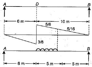
Which one of the following is the influence line for reaction at A of the beam shown in the figure?

Detailed Solution for Test: ILD & Rolling Loads - 3 - Question 3

Using Castigliano’s second theorem

There is no force in member (1) - (2),

Test: ILD & Rolling Loads - 3 - Question 4

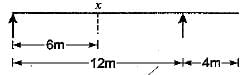
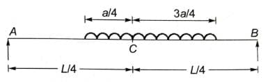
Select the correct influence line diagram for shear force at x of the following beam

Detailed Solution for Test: ILD & Rolling Loads - 3 - Question 4

Maximum shear force is at either of the support due to a point load

Test: ILD & Rolling Loads - 3 - Question 5

The maximum bending moment at the left quarter point of a simple beam due to crossing of UDL of length shorter than the span in the direction left to right, would occur after the load had just crossed the section by

Detailed Solution for Test: ILD & Rolling Loads - 3 - Question 5

Section should divide the load in the same ratio as it divides the span for maximum bending moment.

Length of UDL = a

Load crossed the section by 3a/4

⇒ (wa) / (4 × L/4) = (w × 3/4 a) / (3L/4)

⇒ (wa) / L = (wa) / L

So average load on both side is equal.

Test: ILD & Rolling Loads - 3 - Question 6

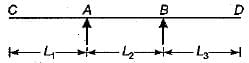
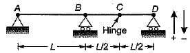
For the continuous beam shown in figure, the influence line diagram for support reaction at D is best represented as

Detailed Solution for Test: ILD & Rolling Loads - 3 - Question 6

The ILD for support reaction at D can be obtained by:giving unit displacement in the direction of reaction. The deflected shape of beam will represent ILD as in figure (c).

Test: ILD & Rolling Loads - 3 - Question 7

Consider the following statements:
1. Influence Line Diagram (ILD) for SF at the fixed end of a cantilever and SFD due to unit load at the free end are same.
2. ILD for BM at the fixed end of a cantilever and BMD due to unit load at the free end are same.
Which of these statements is/are correct?

Detailed Solution for Test: ILD & Rolling Loads - 3 - Question 7

[1] is false because the Influence Line Diagram (ILD) for Shear Force (SF) at the fixed end of a cantilever is not the same as the Shear Force Diagram (SFD) for a unit load at the free end.

[2] is true as the ILD for Bending Moment (BM) at the fixed end of a cantilever matches the Bending Moment Diagram (BMD) for a unit load at the free end. However, this reason does not explain the assertion regarding shear force.

Test: ILD & Rolling Loads - 3 - Question 8

The influence line diagram (ILD) shown is for the member

Test: ILD & Rolling Loads - 3 - Question 9

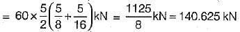
A uniformly distributed line load of 60 kN per metre run of length 5 meters on a girder of span 16 metres. What is the maximum positive shear force at a section 6 metres from the left end.

Detailed Solution for Test: ILD & Rolling Loads - 3 - Question 9

We must first draw the influence line diagram for the SF at the section D,

For maximum positive SF at D, the loading should be applied as shown in the figure.
Maximum positive = load x area of ILD SF at D intensity covered by the load

Test: ILD & Rolling Loads - 3 - Question 10

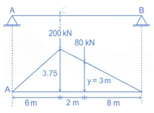
The wheel loads 200 kN and 80 kN spaced 2 m apart move on the span of girder of span 16 metres. What is the maximum bending moment that will occur at a section 6 metres from the left end.

Detailed Solution for Test: ILD & Rolling Loads - 3 - Question 10

To find the maximum bending moment at a section 6 meters from the left end of a 16-meter span girder with loads of 200 kN and 80 kN spaced 2 meters apart:
- Position the Loads: Place the 200 kN load at 6 meters from the left end.
- Calculate Reactions:
- Use equilibrium equations to find reactions at supports.
- Bending Moment at 6m:
- Calculate moment due to 200 kN directly at 6m.
- Add moment due to 80 kN, 2m away.

To get Max BM at C, place 200 kN at C and 80 kN at D, 2 m away from 200 kN an right side.

y/8 = 3.75/10 ⇒ y = 3 m

BM at C = ∑ (ordinate of ILD) × (Load)

= 200 × 3.75 + 80 × 3 = 990 kN.m

∴ Max BM at C will be 990 kN.m

237 tests
Information about Test: ILD & Rolling Loads - 3 Page
In this test you can find the Exam questions for Test: ILD & Rolling Loads - 3 solved & explained in the simplest way possible. Besides giving Questions and answers for Test: ILD & Rolling Loads - 3, EduRev gives you an ample number of Online tests for practice
Download as PDF