Electrical Engineering (EE) Exam  >  Electrical Engineering (EE) Tests  >  Network Theory (Electric Circuits)  >  Test: Dependent & Independent Sources - 1 - Electrical Engineering (EE) MCQ

Test: Dependent & Independent Sources - 1 - Electrical Engineering (EE) MCQ


Test Description

10 Questions MCQ Test Network Theory (Electric Circuits) - Test: Dependent & Independent Sources - 1

Test: Dependent & Independent Sources - 1 for Electrical Engineering (EE) 2025 is part of Network Theory (Electric Circuits) preparation. The Test: Dependent & Independent Sources - 1 questions and answers have been prepared according to the Electrical Engineering (EE) exam syllabus.The Test: Dependent & Independent Sources - 1 MCQs are made for Electrical Engineering (EE) 2025 Exam. Find important definitions, questions, notes, meanings, examples, exercises, MCQs and online tests for Test: Dependent & Independent Sources - 1 below.
Solutions of Test: Dependent & Independent Sources - 1 questions in English are available as part of our Network Theory (Electric Circuits) for Electrical Engineering (EE) & Test: Dependent & Independent Sources - 1 solutions in Hindi for Network Theory (Electric Circuits) course. Download more important topics, notes, lectures and mock test series for Electrical Engineering (EE) Exam by signing up for free. Attempt Test: Dependent & Independent Sources - 1 | 10 questions in 30 minutes | Mock test for Electrical Engineering (EE) preparation | Free important questions MCQ to study Network Theory (Electric Circuits) for Electrical Engineering (EE) Exam | Download free PDF with solutions
Test: Dependent & Independent Sources - 1 - Question 1

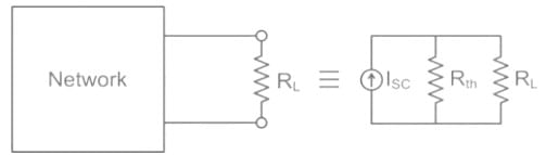
The Norton theorem reduces a circuit to which of the following circuits? 

Detailed Solution for Test: Dependent & Independent Sources - 1 - Question 1

Norton’s Theorem:

Any two terminal bilateral linear DC circuits can be replaced by an equivalent circuit consisting of a current source and a parallel resistor.

Test: Dependent & Independent Sources - 1 - Question 2

In which constant voltage system following operations are performed:

  1. Measure the system current
  2. Compare it with a reference current
  3. Computes and amplifies the error signal

Detailed Solution for Test: Dependent & Independent Sources - 1 - Question 2

Constant Current Control:

  • This method of current control regulates the current by adjusting the duty cycle to maintain a constant output current regardless of changes to the input voltage and output resistance.
  • A power supply operating in constant current mode will compare its reference against the scaled output current. This can be accomplished through the use of a hall effect sensor, a shunt with a differential amplifier, or any other current to voltage conversion method. 
  • The process of comparing the reference against the scaled output current generates an error signal which is then amplified.
Test: Dependent & Independent Sources - 1 - Question 3

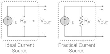
If an ideal voltage source and ideal current source are connected in series, the combination

Detailed Solution for Test: Dependent & Independent Sources - 1 - Question 3

Concept:

Ideal voltage source: An ideal voltage source have zero internal resistance.
Practical voltage source: A practical voltage source consists of an ideal voltage source (VS) in series with internal resistance (RS) as follows.
An ideal voltage source and a practical voltage source can be represented as shown in the figure.

Ideal current source: An ideal current source has infinite resistance. Infinite resistance is equivalent to zero conductance. So, an ideal current source has zero conductance.
Practical current source: A practical current source is equivalent to an ideal current source in parallel with high resistance or low conductance.
Ideal and practical current sources are represented as shown in the below figure.

  • When an ideal voltage source and an ideal current source in series, the combination has an ideal current sources property.
  • Current in the circuit is independent of any element connected in series to it.
     

Explanation:

In a series circuit, the current flows through all the elements is the same. Thus, any element connected in series with an ideal current source is redundant and it is equivalent to an ideal current source only.

In a parallel circuit, the voltage across all the elements is the same. Thus, any element connected in parallel with an ideal voltage source is redundant and it is equivalent to an ideal voltage source only.

Test: Dependent & Independent Sources - 1 - Question 4

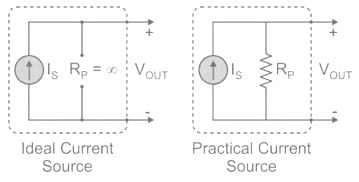
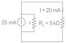
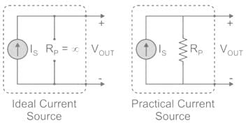
A non-ideal current source of 25 mA is supplying a resistive load of 5 kΩ. If the actual current flowing through the load is 20 mA, then the internal resistance of the source is:

Detailed Solution for Test: Dependent & Independent Sources - 1 - Question 4

Concept:

Ideal Current Source: An ideal current source has infinite resistance. Infinite resistance is equivalent to zero conductance. So, an ideal current source has zero conductance.
Practical Current Source: A practical current source is equivalent to an ideal current source in parallel with high resistance or low conductance.
Ideal and practical current sources are represented as shown in the below figure.


Calculation:


Resistive load RL = 5 × 10³ Ω 
Current through load IL= 20 × 10-3 A
Internal resistance = r
Voltage across load, VL = RL × IL
= 5 × 103 × 20 × 10-3
= 100 V
The net current through internal resistance
r = 25 mA - 20 mA = 5 mA
Voltage across internal resistance = current × r
100 = 5 × 10⁻³ × r
r = 20 kΩ

Test: Dependent & Independent Sources - 1 - Question 5

To neglect a voltage source, the terminal across the source are:

Detailed Solution for Test: Dependent & Independent Sources - 1 - Question 5

To neglect a voltage source, the terminal across the sources are short-circuited. Because ideally, the internal resistance of the voltage source is zero.

To neglect a current source, the terminal across the sources are open-circuited. Because ideally, the internal resistance of the current source is infinite.

Test: Dependent & Independent Sources - 1 - Question 6

Which one of the following must be ensured when two batteries are connected in parallel?

Detailed Solution for Test: Dependent & Independent Sources - 1 - Question 6

When batteries are connected in parallel it must be ensured that they have the same emf to avoid short circuits and to avoid any circulating current between batteries..

Test: Dependent & Independent Sources - 1 - Question 7

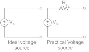
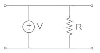
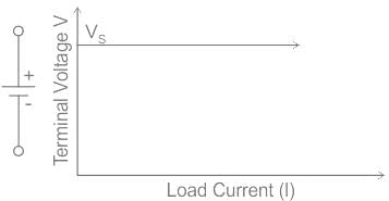
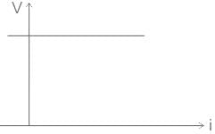
Which one of the following gives the V - I characteristic of an ideal voltage source?

Detailed Solution for Test: Dependent & Independent Sources - 1 - Question 7
  • In every practical voltage source, there is some electrical resistance inside it. This resistance is called the internal resistance of the source.
  • When the terminal of the source is open-circuited, there is no current flowing through it; hence there is no voltage drop inside the source but when the load is connected with the source, current starts flowing through the load as well as the source itself.
  • But in an ideal voltage source, this difference is considered as zero that means there would not be any voltage drop in it when current flows through it and this implies that the internal resistance of an ideal source must be zero.

This can be concluded that voltage across the source remains constant for all values of load current.

The V-I characteristics of an ideal voltage source are shown below.

Ideal case with noise effect,
Considering the effect of noise, Ideal Voltage Source delivers constant voltage irrespective of the value of current through it and V-I characteristics are given as:

Test: Dependent & Independent Sources - 1 - Question 8

The ideal current source will have

Detailed Solution for Test: Dependent & Independent Sources - 1 - Question 8

Ideal Current Source: An ideal current source has infinite resistance. Infinite resistance is equivalent to zero conductance. So, an ideal current source has zero conductance.

Practical Current Source: A practical current source is equivalent to an ideal current source in parallel with a high resistance or low conductance.

Ideal and practical current sources are represented as shown the below figure.

Test: Dependent & Independent Sources - 1 - Question 9

What is the other name for Dependent sources?

Detailed Solution for Test: Dependent & Independent Sources - 1 - Question 9

Dependant sources are also known as Controlled sources as there are controlled by other elements present in the circuit.

Test: Dependent & Independent Sources - 1 - Question 10

In which of the following elements, the voltage does not depend on either the value of the current flowing through the source or its direction?

Detailed Solution for Test: Dependent & Independent Sources - 1 - Question 10

- An independent voltage source delivers a constant voltage regardless of the current flowing through it or the direction of the current.
- This characteristic means its voltage remains unchanged by external circuit elements or conditions.
- In contrast, a resistor and capacitor have voltages dependent on current and other factors like resistance or capacitance.
- An independent current source maintains a constant current, not voltage.
- Hence, the voltage of an independent voltage source (Option D) is unaffected by current variations.

68 videos|88 docs|62 tests
Information about Test: Dependent & Independent Sources - 1 Page
In this test you can find the Exam questions for Test: Dependent & Independent Sources - 1 solved & explained in the simplest way possible. Besides giving Questions and answers for Test: Dependent & Independent Sources - 1, EduRev gives you an ample number of Online tests for practice
Download as PDF