Electronics and Communication Engineering (ECE) Exam  >  Electronics and Communication Engineering (ECE) Tests  >  Sensor & Industrial Instrumentation  >  Test: Sensor & Industrial Instrumentation- 1 - Electronics and Communication Engineering (ECE) MCQ

Test: Sensor & Industrial Instrumentation- 1 - Electronics and Communication Engineering (ECE) MCQ


Test Description

25 Questions MCQ Test Sensor & Industrial Instrumentation - Test: Sensor & Industrial Instrumentation- 1

Test: Sensor & Industrial Instrumentation- 1 for Electronics and Communication Engineering (ECE) 2024 is part of Sensor & Industrial Instrumentation preparation. The Test: Sensor & Industrial Instrumentation- 1 questions and answers have been prepared according to the Electronics and Communication Engineering (ECE) exam syllabus.The Test: Sensor & Industrial Instrumentation- 1 MCQs are made for Electronics and Communication Engineering (ECE) 2024 Exam. Find important definitions, questions, notes, meanings, examples, exercises, MCQs and online tests for Test: Sensor & Industrial Instrumentation- 1 below.
Solutions of Test: Sensor & Industrial Instrumentation- 1 questions in English are available as part of our Sensor & Industrial Instrumentation for Electronics and Communication Engineering (ECE) & Test: Sensor & Industrial Instrumentation- 1 solutions in Hindi for Sensor & Industrial Instrumentation course. Download more important topics, notes, lectures and mock test series for Electronics and Communication Engineering (ECE) Exam by signing up for free. Attempt Test: Sensor & Industrial Instrumentation- 1 | 25 questions in 30 minutes | Mock test for Electronics and Communication Engineering (ECE) preparation | Free important questions MCQ to study Sensor & Industrial Instrumentation for Electronics and Communication Engineering (ECE) Exam | Download free PDF with solutions
Test: Sensor & Industrial Instrumentation- 1 - Question 1

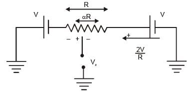
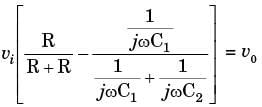
In the potentiometer circuit shown in the figure, the expression for Vx is (2015)

Detailed Solution for Test: Sensor & Industrial Instrumentation- 1 - Question 1
Using KVL,

Test: Sensor & Industrial Instrumentation- 1 - Question 2

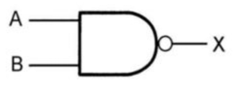
The given circuit represents_____. (2014)
Detailed Solution for Test: Sensor & Industrial Instrumentation- 1 - Question 2

The given circuit represents the NAND gate.

1 Crore+ students have signed up on EduRev. Have you? Download the App
Test: Sensor & Industrial Instrumentation- 1 - Question 3

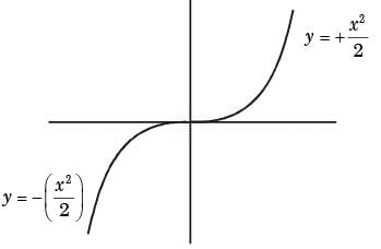
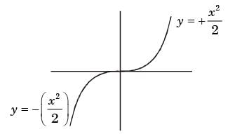
The given graph is the solution of the differential equation (2014)
Detailed Solution for Test: Sensor & Industrial Instrumentation- 1 - Question 3
By looking at the graph, which indicates the solution of differential equation

For option (d)

For > 0

∴ Now integrating both sides.

and for x > 0

Now integrating on both side.sides

Now while plotting the graph of the solution of dy differential equation dy / dx = |x|

we get

Test: Sensor & Industrial Instrumentation- 1 - Question 4

Compared to the upstream to the throat of a venturi meter, which of the following is true (2014)

Detailed Solution for Test: Sensor & Industrial Instrumentation- 1 - Question 4
Comparing the upstream to the throat of a venturi meter, the pressure decreases and velocity increases.
Test: Sensor & Industrial Instrumentation- 1 - Question 5

The pressure at a remote point is measured by an instrumentation system comprising a transmitter [specified accuracy (SA) within ± 0.3%], a relay (SA within ± 1.1%), and a receiver element (SA with ± 0.6%). The maximum possible error of the measurement system will be (2014)

Detailed Solution for Test: Sensor & Industrial Instrumentation- 1 - Question 5
± (α1 + α2 + αs +) = ± 2%. ± (1.1 + 0.3 + 0.6) = ± 2%
Test: Sensor & Industrial Instrumentation- 1 - Question 6

A white noise process X(t) with two-sided power spectral density 1 x 10⁻¹⁰ W/Hz is input to a filter whose magnitude squared response is shown below. (2014)
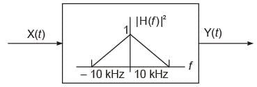
The power of the output process Y(t) is given by

Detailed Solution for Test: Sensor & Industrial Instrumentation- 1 - Question 6
Power output = Area under |H(f)|2

Y(t) = X(t) x 10 kHz

= 10-10 x 104

= 1 x 10⁻⁶ W

(Frequency on the negative side is just a replica of positive frequency.)

Test: Sensor & Industrial Instrumentation- 1 - Question 7

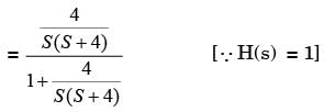
If for the given system (2014)

Then the natural frequency of the system is

Detailed Solution for Test: Sensor & Industrial Instrumentation- 1 - Question 7

∴ Comparing S2 + 4S + 4 with original equation

Now

∴ ωn = 2

Test: Sensor & Industrial Instrumentation- 1 - Question 8

The characteristics of a thermometer measuring ambient temperature is , where Ti and Tα are the indicated and ambient temperatures, respectively, both in °C, and time is in seconds. The -3 dB cut-off frequency in the frequency response of the thermometer is (2011)

Detailed Solution for Test: Sensor & Industrial Instrumentation- 1 - Question 8

=>

=>

Then, ω = 0.5

Test: Sensor & Industrial Instrumentation- 1 - Question 9

For a copper-constantan (Type T) thermocouple, the junction potential E (in μV) at θ°C is given by E = 38.74θ + 3.3 x 10⁻²θ2 + 2.07 x 10⁻⁴ θ3 - 2.2 x 10⁻⁶ θ4 + higher order terms, assuming the cold junction compensation. The sensitivity of thermocouple at 100°C is approximately (2011)

Detailed Solution for Test: Sensor & Industrial Instrumentation- 1 - Question 9
E = 38.74θ + 3.3 x 10⁻²θ2 + 2.07 x 10⁻⁴θ3 - 2.2 x 10⁻⁶ θ4

S = dE / dθ = 38.74 + 6.6 x 10-2 x 100 + 6.21 x 10-3 x (100)2 - 8.8 x 10-6 x (100)3 + ...

= [42.75 + higher order term] μV/°C.

Test: Sensor & Industrial Instrumentation- 1 - Question 10

A turbine flowmeter is rotating at 72 rpm. The flux ψ linked to the nearby magnet and coil assembly is given by ψ(θ) = 3 + cos (4θ) mWb, where θ is the angular position (in radian). The amplitude and frequency of the output voltage signal, respectively, are (2011)

Detailed Solution for Test: Sensor & Industrial Instrumentation- 1 - Question 10
ψ(θ) = 3 + cos 4θ

∴ f = 1.2 rev/sec

= 4 sin4θ.(2πf)

V = 8πf.sin 4θ

V = 30.2 sin 4θ

Frequency of o/p voltage = 4 x f = 4.8 Hz

Amplitude = 30.2 mV.

Test: Sensor & Industrial Instrumentation- 1 - Question 11

Match the following: (2010)

Detailed Solution for Test: Sensor & Industrial Instrumentation- 1 - Question 11
Radiation Pyrometer → Iemf

Gyroscope → Angular velocity

Test: Sensor & Industrial Instrumentation- 1 - Question 12

The seismic mass of an accelerometer oscillates sinusoidally at 100 Hz with a maximum displacement of 10 mm from its mean position. The peak acceleration of the seismic mass is (2010)

Detailed Solution for Test: Sensor & Industrial Instrumentation- 1 - Question 12
Peak acceleration of seismic mass

= - xm ω2 = - 10-3 (2πf)2

= - 10-3 (2 x 3.14 x 100)2

= - 10-3 x (628)2

= 3943.84 m/s2

Test: Sensor & Industrial Instrumentation- 1 - Question 13

A differential pressure transmitter is used to measure the flow rate in a pipe. Due to aging, the sensitivity of the pressure transmitter is reduced by 5%. All other aspects of the flow meter remaining constant; change in the sensitivity of the flow measurement is (2010)

Detailed Solution for Test: Sensor & Industrial Instrumentation- 1 - Question 13
Change is the sensitivity of the transmitter

= Sensitivity of flow measurement

Sensitivity is reduced by 5%. Since other parameters are constant, hence sensitivity of flow measurement also reduces by 5%.

Test: Sensor & Industrial Instrumentation- 1 - Question 14

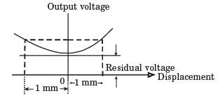
An LVDT is supplied with a sinusoidal voltage of amplitude 5 V and frequency 1 kHz. The output is connected to an ac voltmeter. The reading of the voltmeter is 1 V for a displacement of 1 mm from the null position. When the displacement is 1 mm in the opposite direction from the null position, the reading of the voltmeter is (2009)

Detailed Solution for Test: Sensor & Industrial Instrumentation- 1 - Question 14
At both sides of origin, voltages at the displacement of 1 mm would be the same.

Test: Sensor & Industrial Instrumentation- 1 - Question 15

A piezoelectric type pressure sensor has a sensitivity of 1 mV/kPa and a bandwidth of 300 Hz to 300 kHz. For a constant (dc) pressure of 100 kPa, the steady-state output of the sensor in millivolt is____. (2016)


Detailed Solution for Test: Sensor & Industrial Instrumentation- 1 - Question 15

For constant (dc) pressure piezoelectric sensor will not respond, so the output voltage is 0 Volt.

Test: Sensor & Industrial Instrumentation- 1 - Question 16

A quantity x is calculated by using the formula

The measured values are p = 9, q = 6, r = 0.5

Assume that the measurement errors in p, q, and r are independent. The absolute maximum error in the measurement of each of the three quantities is ε. The absolute maximum error in the calculated value of x is

Detailed Solution for Test: Sensor & Industrial Instrumentation- 1 - Question 16

Test: Sensor & Industrial Instrumentation- 1 - Question 17

The response of a first-order measurement system to a unit step input is 1 - e-0.5t, where t is in seconds. A ramp of 0.1 units per second is given as the input to this system. The error in the measured value after transients have died down is (2009)

Detailed Solution for Test: Sensor & Industrial Instrumentation- 1 - Question 17

= 0.1 unit

Test: Sensor & Industrial Instrumentation- 1 - Question 18

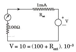
A galvanometer with internal resistance 100Ω and full-scale current 1 mA is used to realize a dc voltmeter with a full-scale range of 1V. The full-scale range of this voltmeter can be extended to 10V by connecting an external resistance of value (2009)

Detailed Solution for Test: Sensor & Industrial Instrumentation- 1 - Question 18

V = 10 = (100 + Rext ). 10-3

Rext = 9.9 kΩ

Test: Sensor & Industrial Instrumentation- 1 - Question 19

A stroboscopic system is used for measuring the speed of a rotating shaft. The shaft has one target mark on it. The maximum strobe rate at which synchronism is achieved is r1 flashes per minute. The next lower flash rate at which synchronism is achieved is r2 flashes per minute. The speed of the shaft in rpm is (2009)

Detailed Solution for Test: Sensor & Industrial Instrumentation- 1 - Question 19
Speed of the shaft,

where fm = highest flashing rate

f1 = lowest flashing rate

m = number of flashing frequency

= 2

then,

Test: Sensor & Industrial Instrumentation- 1 - Question 20

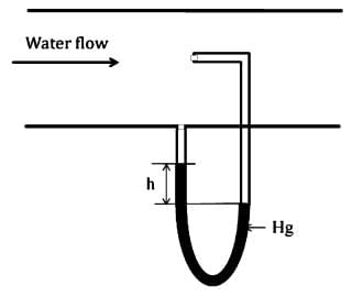
The velocity of water flow (density 1000 kg/m3) in a horizontal pipe is measured using the PITOT tube shown below. The fluid in the U -tube manometer is mercury with a density of 13534 kg/m3. Assume g = 9.81 m/s2. If the height difference (h) is measured as 94.1 mm, the velocity of flow of water in m/s is___. (2016)

Detailed Solution for Test: Sensor & Industrial Instrumentation- 1 - Question 20

The velocity of flow of water

h = 1.18

So, the velocity of the flow of water is 4.81 m/sec.

Test: Sensor & Industrial Instrumentation- 1 - Question 21

The values of the material constant p for thermistors P and Q are 4000 K and 3000 K, respectively. The resistance of each thermistor at 298 K is 2 kΩ. At 373 K, the ratio of the resistance of thermistor P to that of thermistor Q will be closest to (2009)

Detailed Solution for Test: Sensor & Industrial Instrumentation- 1 - Question 21

For thermistor P,

= 0.1345

For thermistor Q,

= 0.264

Then, the ratio of the resistance of thermistor P to thermistor Q

Test: Sensor & Industrial Instrumentation- 1 - Question 22

The sensitivity is (2009)

Detailed Solution for Test: Sensor & Industrial Instrumentation- 1 - Question 22

=>

=>

and

=>

Test: Sensor & Industrial Instrumentation- 1 - Question 23

The speed of a gear having 60 teeth is measured using a proximity sensor. The output of the proximity sensor is fed to a counter with a gating time of 1s. The counter indicates a value of 120. The speed at which the gear is rotating is (2008)

Detailed Solution for Test: Sensor & Industrial Instrumentation- 1 - Question 23

Test: Sensor & Industrial Instrumentation- 1 - Question 24

A piezoelectric type accelerometer has a sensitivity of 100 mV/g. The transducer is subjected to a constant acceleration of 5g. The steady-state output of the transducer will be (2008)

Detailed Solution for Test: Sensor & Industrial Instrumentation- 1 - Question 24
Steady state output = sensitivity x acceleration

= 100 mV/g x 5g

= 0.5 V.

Test: Sensor & Industrial Instrumentation- 1 - Question 25

A differential amplifier shown below has a differential mode gain of 100 and a CMRR of 40 dB. If V1 = 0.55 V and V2 = 0.45 V, output V0 is (2008)

Detailed Solution for Test: Sensor & Industrial Instrumentation- 1 - Question 25

or

or Vc = 1

= 100 (0.10) + 0.5 (1)

= 10.5 volts

23 videos|24 docs|29 tests
Information about Test: Sensor & Industrial Instrumentation- 1 Page
In this test you can find the Exam questions for Test: Sensor & Industrial Instrumentation- 1 solved & explained in the simplest way possible. Besides giving Questions and answers for Test: Sensor & Industrial Instrumentation- 1, EduRev gives you an ample number of Online tests for practice

Top Courses for Electronics and Communication Engineering (ECE)

Download as PDF

Top Courses for Electronics and Communication Engineering (ECE)