RSMSSB JE Electrical Mock Test - 4 - Electrical Engineering (EE) MCQ
30 Questions MCQ Test - RSMSSB JE Electrical Mock Test - 4

Who among the following was the founder of Niranjani sect?

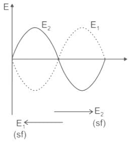
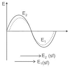
In order to control the speed of a 3-phase slip ring induction motor through injected voltage in its rotor circuit, this voltage and the rotor voltage should essentially be


 will be

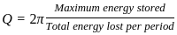
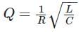
A series RLC circuit has a resonance frequency of 1 KHz and a quality factor Q = 100. If each of R, L, C doubled from its original value. The new quality factor Q of the circuit is
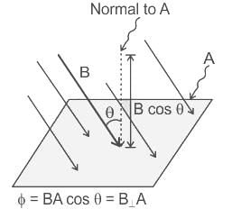
The magnetic flux through a 150 turns coil increases at the rate of 0.08 wb/s. What is the induced EMF between the ends of the coil?


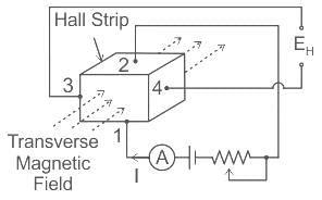
Which of the following transductions is done by the Hall effect device as a transducer?

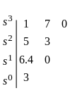
The number of roots of s3 + 5s2 + 7s + 3 = 0 in the left half of the s-plane is


A transformer can have regulation closer to zero on __________.

A damper winding is used in a synchronous motor for-
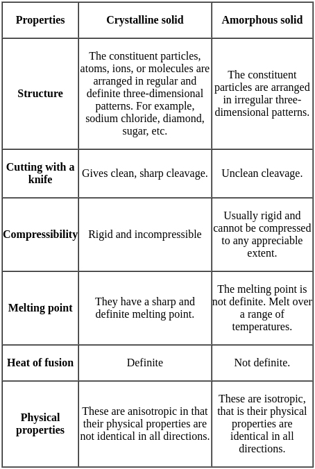
What are the materials which exhibit electric polarization even in the absence of an applied electrical field?
Rajasthan is endowed with a solar radiation intensity of around_______Kwh/sq-m/day.
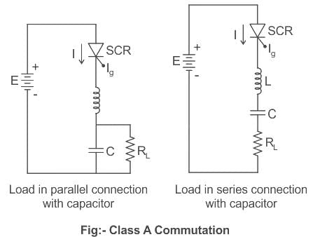
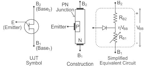
UJT is used for which of the following applications?


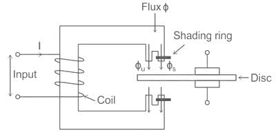
Torque produced in shaded pole structure induction type relay is:
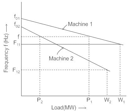
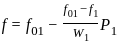
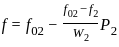
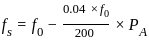
Two synchronous generators G1 and G2 rated 200 MW and 400 MW respectively are operated in parallel to supply a total load of 300 MW. If the governors in both the machines are set to a droop of 4%, what would be the individual power supplied by each generator?


 .... (1)

 .... (2)
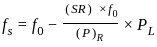
 .............(2)
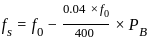 .............(3)
 ..................(4)
Important Questions for RSMSSB JE Electrical Mock Test - 4
RSMSSB JE Electrical Mock Test - 4 MCQs with Answers
Online Tests for RSMSSB JE Electrical Mock Test - 4
|
© EduRev
|
Education Revolution
|


|


within 7 days!