TANGEDCO AE EE Full Test - 2 - Electrical Engineering (EE) MCQ
30 Questions MCQ Test - TANGEDCO AE EE Full Test - 2


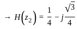
In the Laurent expansion of 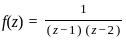 valid in the region 1 < |z| < 2, the co-efficient of
  is
is
valid in the region 1 < |z| < 2, the co-efficient of is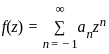
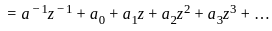
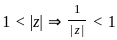
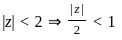
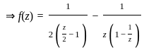
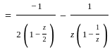
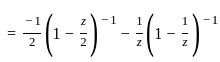
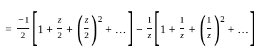
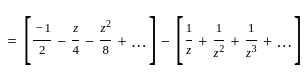
 is -1
is -1
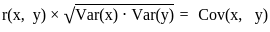
Let X and Y be a bivariate random variable with correlation coefficient 1/2, and standard deviation 2 and 3 respectively, then Cov (X,Y) is
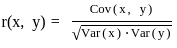
 (2)2 = 4
 (3)2 = 9
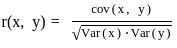
When an alternating current passes through an ohmic resistance, the electric power converted into heat is
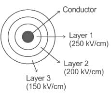
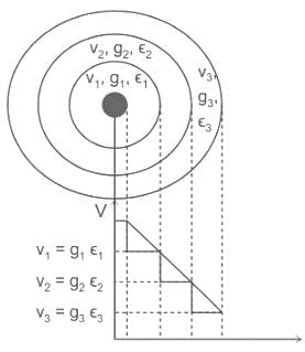
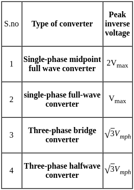
Three insulating materials with breakdown strength 250 kV/cm, 200 kV/cm, 150 kV/cm and permittivities of 2.5, 3.0 and 3.5 are used in a single core cable. If the factor of safety for the materials is 5, the location of the materials with respect to the core of the cable will be
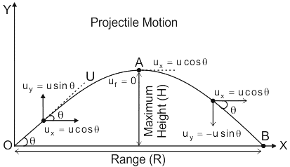
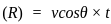
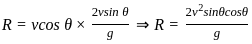
If a projectile is thrown with velocity 'v' and makes an angle 'θ' with the x-axis then the horizontal range of the projectile is given by the formula ______________.

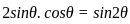 (By using trigonometric relation)
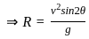
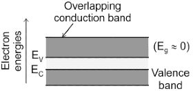
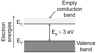
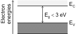
Behaviour of conductors, semiconductors and insulators is explained on the basis of
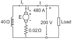
A DC shunt generator delivers 480 A at 200 V. Its armature and field winding resistance are 0.02 Ω and 40 Ω respectively. What will be the value of generated emf?


A d.c. series generator has a no load induced e.m.f. of 10 volts. If its speed is doubled, the no load induced e.m.f. is
Bounded-input bounded-output stability implies asymptotic stability for
1. Completely controllable system
2. Completely observable system
3. Uncontrollable system
4. Unobservable system
Which of the above statements are correct?A uniform plane wave with an intensity of magnetic field 6 A/m is travelling in a lossless non magnetic medium(ϵ = 36ϵ0). The magnitude of associated electric field is:


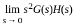
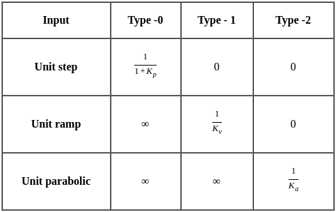
 steady-state error for parabolic-input.
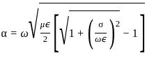
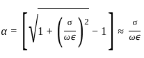
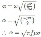
An electromagnetic wave is transmitted into a conducting medium of conductivity σ. The depth of penetration is


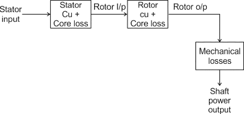
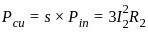
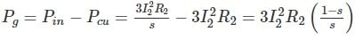
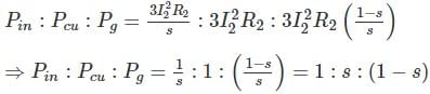
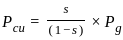
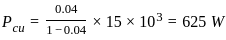
The rotor power output of 3-phase induction motor is 15 kW. The rotor copper losses at a slip of 4% will be -

To limit the line charging current, long distance EHV lines are connected with ________ at both ends.
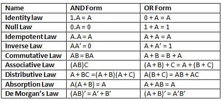
The minimum number of NAND gates required to implement  is:
is:
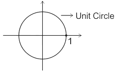
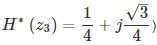
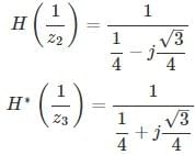
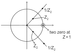
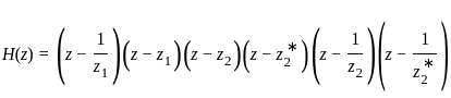
What will be the order of the odd length even symmetric FIR impulse response if it is
known that there is a zero at  and second zero at z = 1.

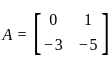
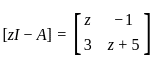
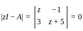
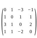
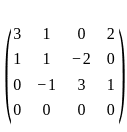
Determine the characteristic equation for the system matrix of a discrete system given below.

The characteristic equation of a feedback control system is
2s4 + s3 + 2s2 + 5s + 10 = 0
The number of roots in the right half of the s-plane is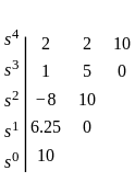
In the circuit shown, an ideal switch S is operated at 100 KHz with a duty ratio of 50%. Given that Δ icis 1.6 A peak to peak and Iois 5 A dc, the peak current in S is
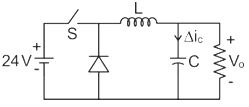
 is
is
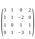

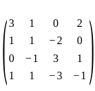

 R2 - (R1/3)
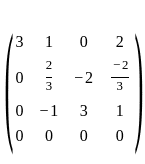
 R3 + (3/2)R2
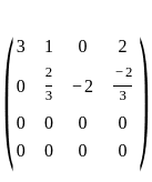
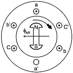
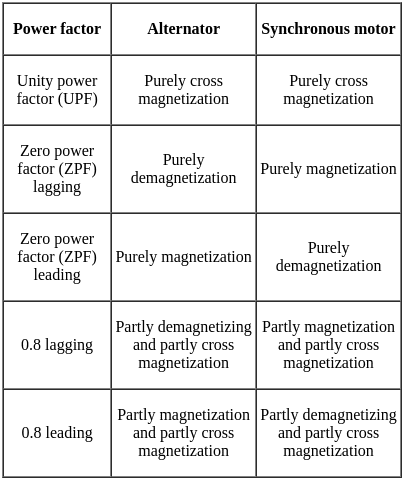
Armature reaction in a synchronous generator at rated voltage and zero power factor leading is


Important Questions for TANGEDCO AE EE Full Test - 2
TANGEDCO AE EE Full Test - 2 MCQs with Answers
Online Tests for TANGEDCO AE EE Full Test - 2
|
© EduRev
|
Education Revolution
|


|


