Electrical Engineering (EE) Exam  >  Electrical Engineering (EE) Tests  >  Network Theory (Electric Circuits)  >  Test: Series Circuits & Parallel Networks - Electrical Engineering (EE) MCQ

Test: Series Circuits & Parallel Networks - Electrical Engineering (EE) MCQ


Test Description

30 Questions MCQ Test Network Theory (Electric Circuits) - Test: Series Circuits & Parallel Networks

Test: Series Circuits & Parallel Networks for Electrical Engineering (EE) 2024 is part of Network Theory (Electric Circuits) preparation. The Test: Series Circuits & Parallel Networks questions and answers have been prepared according to the Electrical Engineering (EE) exam syllabus.The Test: Series Circuits & Parallel Networks MCQs are made for Electrical Engineering (EE) 2024 Exam. Find important definitions, questions, notes, meanings, examples, exercises, MCQs and online tests for Test: Series Circuits & Parallel Networks below.
Solutions of Test: Series Circuits & Parallel Networks questions in English are available as part of our Network Theory (Electric Circuits) for Electrical Engineering (EE) & Test: Series Circuits & Parallel Networks solutions in Hindi for Network Theory (Electric Circuits) course. Download more important topics, notes, lectures and mock test series for Electrical Engineering (EE) Exam by signing up for free. Attempt Test: Series Circuits & Parallel Networks | 30 questions in 30 minutes | Mock test for Electrical Engineering (EE) preparation | Free important questions MCQ to study Network Theory (Electric Circuits) for Electrical Engineering (EE) Exam | Download free PDF with solutions
Test: Series Circuits & Parallel Networks - Question 1

In a series circuit, which of the parameters remain constant across all circuit elements such as resistor, capacitor and inductor?

Detailed Solution for Test: Series Circuits & Parallel Networks - Question 1

In a series circuit, the current across all elements remain the same and the total volt-age of the circuit is the sum of the voltages across all the elements.

Test: Series Circuits & Parallel Networks - Question 2

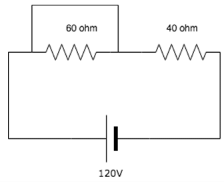
Voltage across the 60 Ω resistor is ______.
Detailed Solution for Test: Series Circuits & Parallel Networks - Question 2
  • The 60 ohm resistance is shorted since current always chooses the low resistance path. So, whole of the current will flow through the alternative route and there will be 0 current through 60Ω resistance.
  • As, Voltage across short circuit is equal to zero, hence voltage across the resistor is 0.
1 Crore+ students have signed up on EduRev. Have you? Download the App
Test: Series Circuits & Parallel Networks - Question 3

Calculate the resistance between A and B.
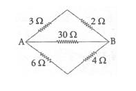
1222093

Detailed Solution for Test: Series Circuits & Parallel Networks - Question 3

Test: Series Circuits & Parallel Networks - Question 4

 Find the voltage across the 6 ohm resistor.

Detailed Solution for Test: Series Circuits & Parallel Networks - Question 4

Total current = 150/(6+12+15) = 4.55A.

V across 6 ohm = Total current x resistance

= 4.55 * 6 = 27.24V.

Test: Series Circuits & Parallel Networks - Question 5

If there are two bulbs connected in series and one blows out, what happens to the other bulb?

Detailed Solution for Test: Series Circuits & Parallel Networks - Question 5

Since the two bulbs are connected in series, if the first bulb burns out there is a break in the circuit and hence the second bulb does not glow.

Test: Series Circuits & Parallel Networks - Question 6

 Voltage across a series resistor circuit is proportional to?

Detailed Solution for Test: Series Circuits & Parallel Networks - Question 6

V=IR hence voltage across a series resistor circuit is proportional to the value of the resistance because current remains same in series circuit.

Test: Series Circuits & Parallel Networks - Question 7

 Many resistors connected in series will_______

Detailed Solution for Test: Series Circuits & Parallel Networks - Question 7

In a series circuit, the current remains the same across all resistors hence the voltage divides proportionally among all resistors.

Test: Series Circuits & Parallel Networks - Question 8

 What is the voltage measured across a series short?

Detailed Solution for Test: Series Circuits & Parallel Networks - Question 8

A short is just a wire. The potential difference between two points of a wire is zero hence the voltage measured is equal to zero.

Test: Series Circuits & Parallel Networks - Question 9

What happens to the current in the series circuit if the resistance is doubled?

Detailed Solution for Test: Series Circuits & Parallel Networks - Question 9

Current is inversely proportional to resistance so resistance increased 2 times means current is decreased 2 times.

Test: Series Circuits & Parallel Networks - Question 10

 If two bulbs are connected in parallel and one bulb blows out, what happens to the other bulb?

Detailed Solution for Test: Series Circuits & Parallel Networks - Question 10

 In a parallel circuit, if one bulb blows out, it acts as an open circuit. Current does not flow in that branch but it continues to flow in the other branch hence the bulb continues to glow.

Test: Series Circuits & Parallel Networks - Question 11

Calculate the current across the 20 ohm resistor.

Detailed Solution for Test: Series Circuits & Parallel Networks - Question 11

I = V/R. Since in parallel circuit, voltage is same across all resistors. Hence, across the 20 ohm resistor, V = 200V so I = 200/20  = 10A

Test: Series Circuits & Parallel Networks - Question 12

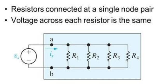
In a parallel circuit, with a number of resistors, the voltage across each resistor is ________

Detailed Solution for Test: Series Circuits & Parallel Networks - Question 12

 In parallel circuits, the current across the circuits vary whereas the voltage remains the same.

Test: Series Circuits & Parallel Networks - Question 13

 Calculate the total current in the circuit.

Detailed Solution for Test: Series Circuits & Parallel Networks - Question 13
  • The 1 ohm and 2-ohm resistor are in series which is in parallel to the 3-ohm resistor.
  • The equivalent of these resistances is in series with the 4 ohms and 5-ohm resistor.
  • Total R= 10.5 ohm. I=V/R= 120/10.5= 11.42A.
Test: Series Circuits & Parallel Networks - Question 14

The voltage across the open circuit is?

Detailed Solution for Test: Series Circuits & Parallel Networks - Question 14

The voltage across all branches in a parallel circuit is the same as that of the source voltage. Hence the voltage across the 10 ohm resistor and the open circuit is the same=100V.

Test: Series Circuits & Parallel Networks - Question 15

The voltage across the short is?

Detailed Solution for Test: Series Circuits & Parallel Networks - Question 15

The voltage across a short is always equal to zero whether it is connected in series or parallel.

Test: Series Circuits & Parallel Networks - Question 16

If the current through the x ohm resistance in the circuit is 5A, find the value of x.

Detailed Solution for Test: Series Circuits & Parallel Networks - Question 16

R=V/I. In this circuit I=5A and V=135V. Therefore, R=135/5=27 ohm.

Test: Series Circuits & Parallel Networks - Question 17

The currents entering in the three branches of a parallel circuit are 3A, 4A and 5A. What is the current leaving it?

Detailed Solution for Test: Series Circuits & Parallel Networks - Question 17

The total current leaving a node is the same as the current that enters it. Total I=I1+I2+I3=3+4+5=12A.

Test: Series Circuits & Parallel Networks - Question 18

The total resistance between A and B are?

Detailed Solution for Test: Series Circuits & Parallel Networks - Question 18

The resistors are connected in parallel, hence the equivalent resistance= 1/(1/20=1/20+1/20+1/20)=5ohm.

Test: Series Circuits & Parallel Networks - Question 19

Calculate the equivalent resistance between A and B.
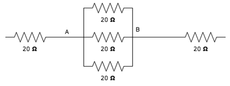
Detailed Solution for Test: Series Circuits & Parallel Networks - Question 19

Test: Series Circuits & Parallel Networks - Question 20

Batteries are generally connected in ______.

Detailed Solution for Test: Series Circuits & Parallel Networks - Question 20

Batteries can be connected in series or parallel depending on the desired electrical outcome. When connected in series, the voltages add up, providing a higher total voltage, which is useful when higher voltage is needed. Conversely, connecting batteries in parallel increases the total current capacity while maintaining the same voltage, which is beneficial when a higher current is required. Therefore, batteries are generally connected in either series or parallel based on the specific requirements.

Test: Series Circuits & Parallel Networks - Question 21

 In a _________ circuit, the total resistance is greater than the largest resistance in the circuit.

Detailed Solution for Test: Series Circuits & Parallel Networks - Question 21

 In series circuits the total resistance is the sum of all the resistance in the circuit, hence the total is greater than the largest resistance.

Test: Series Circuits & Parallel Networks - Question 22

What is the current through R1 and R2 in the following diagram?
Circuit1.JPG

Detailed Solution for Test: Series Circuits & Parallel Networks - Question 22

Since each resistor is connected across a 5V source, we calculate the current through each resistor individually.

  1. Current through the 5-ohm resistor:

    I1=VR1=5V5Ω=1AI_1 = \frac{V}{R_1} = \frac{5 \, \text{V}}{5 \, \Omega} = 1 \, \text{A}
  2. Current through the 3-ohm resistor:

    I2=VR2=5V3Ω1.67AI_2 = \frac{V}{R_2} = \frac{5 \, \text{V}}{3 \, \Omega} \approx 1.67 \, \text{A}

Final Answer:

  • The current through the 5-ohm resistor is 1 A.
  • The current through the 3-ohm resistor is approximately 1.67 A.

The total current drawn from the 5V source would be the sum of these currents:

Itotal=I1+I2=1A+1.67A2.67AI_{\text{total}} = I_1 + I_2 = 1 \, \text{A} + 1.67 \, \text{A} \approx 2.67 \, \text{A}

So, the correct answer for the current through the 3-ohm resistor is 1.67 A, and not 3.125 A.

Test: Series Circuits & Parallel Networks - Question 23

Calculate the equivalent resistance between A and B.

Detailed Solution for Test: Series Circuits & Parallel Networks - Question 23
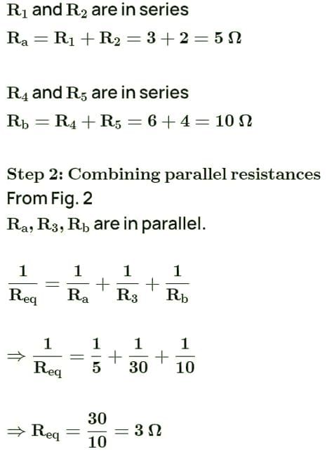
  • 3 and 2 ohm resistors are in series, So 3+2 = 5ohm
  • 5 and 5 ohm resistors are in parallel. So 5 || 5 = 2.5ohms
  • 2.5 and1.5ohm resistors are in series. So 2.5+1.5 = 4ohms
  • Finally, 4 and 4ohm resistors are in parallel. So 4 || 4 = 2ohms.
    That is resistance across A and B terminals is 2 ohms
Test: Series Circuits & Parallel Networks - Question 24

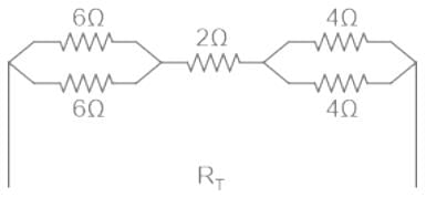
A circuit has a resistor with a resistance of 3Ω followed by three parallel branches, each holding a resistor with a resistance of 5Ω. What is the total equivalent resistance of the circuit?

Detailed Solution for Test: Series Circuits & Parallel Networks - Question 24

Test: Series Circuits & Parallel Networks - Question 25

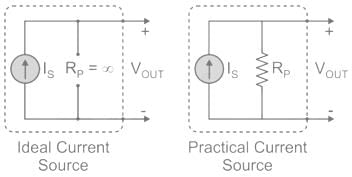
A practical current source consists of

Detailed Solution for Test: Series Circuits & Parallel Networks - Question 25

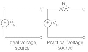
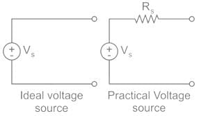
Ideal Voltage Source: An ideal voltage source has zero internal resistance.

Practical Voltage Source: A practical voltage source consists of an ideal voltage source (VS) in series with internal resistance (RS).

An ideal voltage source and a practical voltage source can be represented as shown in the figure.

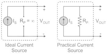
Ideal Current Source: An ideal voltage source has infinite resistance. Infinite resistance is equivalent to zero conductance. So, an ideal current source has zero conductance.

Practical Current Source: A practical current source is equivalent to an ideal current source in parallel with a high resistance or low conductance.

Ideal and practical current sources are represented as shown the below figure.

Test: Series Circuits & Parallel Networks - Question 26

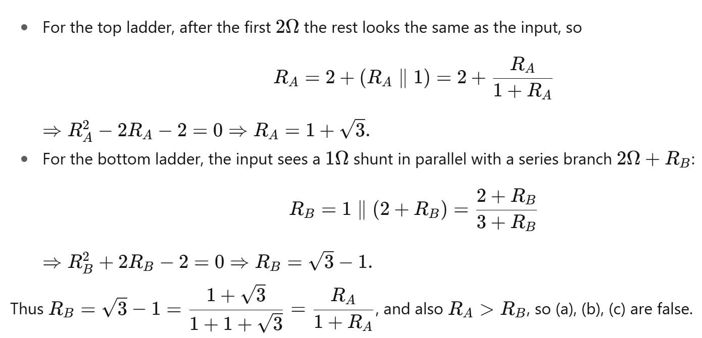
RA and RB are the input resistances of circuits as shown below. The circuits extend infinitely in the direction shown. Which one of the following statements is TRUE?
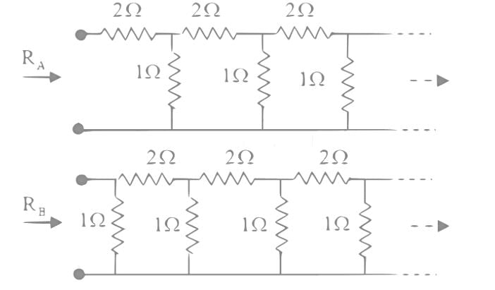
Test: Series Circuits & Parallel Networks - Question 27

A network of resistors is connected to a 16 V battery with an internal resistance of 1 Ω, as shown in the figure. Compute the equivalent resistance of the network.
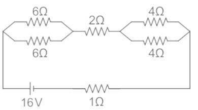
Detailed Solution for Test: Series Circuits & Parallel Networks - Question 27

The circuit after removing the voltage source

The total resistance of the new circuit will be the equivalent resistance of the network.

Req = Rt = 3 + 2 + 2 = 7 Ω 

The equivalent resistance of the network is 7 Ω.

Test: Series Circuits & Parallel Networks - Question 28

If n identical resistance, each of resistance R, are connected in parallel, the equivalent resistance is:

Detailed Solution for Test: Series Circuits & Parallel Networks - Question 28

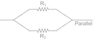
Resistances in parallel combination: When two or more resistances are connected across different branches such that the potential drop across them are the same, they are said to be in parallel connection.

The net resistance/equivalent resistance (R) of resistances in parallel is given by:
Equivalent resistance (R): 
EXPLANATION:
If n resistance connected in parallel the,

Hence,

Test: Series Circuits & Parallel Networks - Question 29

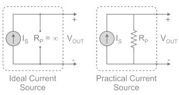
A practical current source is equivalent to an ideal current source in parallel with ________

Detailed Solution for Test: Series Circuits & Parallel Networks - Question 29

Concept : 

Ideal current source: an ideal current source has infinite resistance. Infinite Resistance is equivalent to zero conductance. 

Practical current source: Practical current source is equivalent to the ideal current source in parallel with high resistance or low conductance.

Ideal and practical current sources are represented as given below :

Test: Series Circuits & Parallel Networks - Question 30

An ideal current source has

Detailed Solution for Test: Series Circuits & Parallel Networks - Question 30

Ideal current source: An ideal current source has infinite resistance. Infinite resistance is equivalent to zero conductance. So, an ideal current source has zero conductance.

Practical current source: A practical current source is equivalent to an ideal current source in parallel with high resistance or low conductance.

Ideal and practical current sources are represented as shown in the below figure:

Important Points

Ideal voltage sourceAn ideal voltage source have zero internal resistance.

Practical voltage source: A practical voltage source consists of an ideal voltage source (VS) in series with internal resistance (RS) as follows.

An ideal voltage source and a practical voltage source can be represented as shown in the figure.

68 videos|85 docs|62 tests
Information about Test: Series Circuits & Parallel Networks Page
In this test you can find the Exam questions for Test: Series Circuits & Parallel Networks solved & explained in the simplest way possible. Besides giving Questions and answers for Test: Series Circuits & Parallel Networks, EduRev gives you an ample number of Online tests for practice

Top Courses for Electrical Engineering (EE)

Download as PDF

Top Courses for Electrical Engineering (EE)