Physics Exam  >  Physics Tests  >  Topic wise Tests for IIT JAM Physics  >  Digital Electronics MCQ Level- 1 - Physics MCQ

Digital Electronics MCQ Level- 1 - Physics MCQ


Test Description

10 Questions MCQ Test Topic wise Tests for IIT JAM Physics - Digital Electronics MCQ Level- 1

Digital Electronics MCQ Level- 1 for Physics 2024 is part of Topic wise Tests for IIT JAM Physics preparation. The Digital Electronics MCQ Level- 1 questions and answers have been prepared according to the Physics exam syllabus.The Digital Electronics MCQ Level- 1 MCQs are made for Physics 2024 Exam. Find important definitions, questions, notes, meanings, examples, exercises, MCQs and online tests for Digital Electronics MCQ Level- 1 below.
Solutions of Digital Electronics MCQ Level- 1 questions in English are available as part of our Topic wise Tests for IIT JAM Physics for Physics & Digital Electronics MCQ Level- 1 solutions in Hindi for Topic wise Tests for IIT JAM Physics course. Download more important topics, notes, lectures and mock test series for Physics Exam by signing up for free. Attempt Digital Electronics MCQ Level- 1 | 10 questions in 30 minutes | Mock test for Physics preparation | Free important questions MCQ to study Topic wise Tests for IIT JAM Physics for Physics Exam | Download free PDF with solutions
Digital Electronics MCQ Level- 1 - Question 1

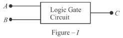
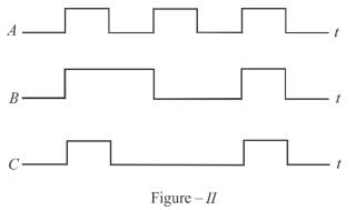
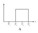
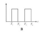
Figure-I shows a logic circuit with two inputs A and B and output C. The voltage incorrect waveform of A, B and C are shown in figure-II. The logic circuit is :
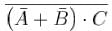
Detailed Solution for Digital Electronics MCQ Level- 1 - Question 1

From the waveform A, B and C, it is clear that output is 1, if both B and A are 1 otherwise zero.
C = A . B
The correct answer is: AND gate

Digital Electronics MCQ Level- 1 - Question 2

In Boolean Algebra, will be equal to.

Detailed Solution for Digital Electronics MCQ Level- 1 - Question 2


The correct answer is: 

1 Crore+ students have signed up on EduRev. Have you? Download the App
Digital Electronics MCQ Level- 1 - Question 3

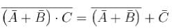
When an input electrical signal A = 10100 is applied to a NOT gate, its output signal  is :

Detailed Solution for Digital Electronics MCQ Level- 1 - Question 3

NOT gate implies output  where A is the input.
The correct answer is: 01011

Digital Electronics MCQ Level- 1 - Question 4

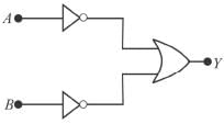
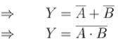
The output Y from the following logic gate circuit will be :

Detailed Solution for Digital Electronics MCQ Level- 1 - Question 4


The correct answer is: 

Digital Electronics MCQ Level- 1 - Question 5

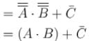
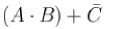
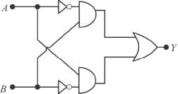
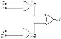
The Boolean expression of the output Y in terms of the inputs A and B for the circuit shown in the following figure is.

Detailed Solution for Digital Electronics MCQ Level- 1 - Question 5

Equivalent circuit is


The correct answer is:  

Digital Electronics MCQ Level- 1 - Question 6

The binary number 110000111101 corresponds to a hexadecimal number. 

Detailed Solution for Digital Electronics MCQ Level- 1 - Question 6

Hexadecimal is written with 16 numbers starting from 0, i.e., 0, 1,2, 3,...14, 15. The number 10 → A; 11 → B; 12 → C; 13 → D; 14 → E; 15 → F in place of two digits. To convert binary number in hexadecimal make the pairs of four numbers starting from right. Then convert them in decimal then hexadecimal e.g. (110000111101) ⇔ [(1100) (0011) (1101)2] in binary number ⇔ [(12) (3) (13) ] in decimal
= C3D is the equivalent hexadecimal number
The correct answer is: C3D

Digital Electronics MCQ Level- 1 - Question 7

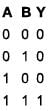
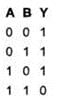
Figure I shows a two input type of logic circuit where A and B are the inputs and C is the output. The truth table of the logic gate is shown in Figure II.

Detailed Solution for Digital Electronics MCQ Level- 1 - Question 7

NAND implies 
The correct answer is: NAND

Digital Electronics MCQ Level- 1 - Question 8

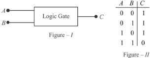
Which one of the following logic gate does the given truth table represent?

Detailed Solution for Digital Electronics MCQ Level- 1 - Question 8

⇒ AND gate implies Y=A.B.
The correct answer is: AND

Digital Electronics MCQ Level- 1 - Question 9

The given figure shows the wave forms for two inputs A and B and that for the output V of logic circuit. The logic circuit is :
 

Detailed Solution for Digital Electronics MCQ Level- 1 - Question 9

From the response of A, B and C, it is clear that C = A.B, hence, an AND gate.
The correct answer is: AND gate

Digital Electronics MCQ Level- 1 - Question 10

The truth table for the input NAND gate is given by :

Detailed Solution for Digital Electronics MCQ Level- 1 - Question 10

NAND gate is given as 
The correct answer is:

217 tests
Information about Digital Electronics MCQ Level- 1 Page
In this test you can find the Exam questions for Digital Electronics MCQ Level- 1 solved & explained in the simplest way possible. Besides giving Questions and answers for Digital Electronics MCQ Level- 1, EduRev gives you an ample number of Online tests for practice
Download as PDF