Practice Test: Electronics Engineering (ECE)- 3 - Electronics and Communication Engineering (ECE) MCQ
30 Questions MCQ Test - Practice Test: Electronics Engineering (ECE)- 3

“Wanted a two bedroom flat in the court area for immediate possession” - An Advertisement.
Assumptions:
I. Flats are available in the court area
II. Some people will respond to the advertisement
III. It is a practice to give such an advertisement
Assumptions:
I. Flats are available in the court area
II. Some people will respond to the advertisement
III. It is a practice to give such an advertisement
Which of the following is most similar in meaning to the given word
DIRE
DIRE

In the question given below, the sentence has a part printed in bold. That part may contain a grammatical error. Replace that part with four choices given below:
The famous playwright has been in the sick bed from the last one week.
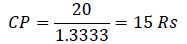
 %. If the first liquid is costlier than the second by Rs 7. Find the sum of costs of both the liquids.
 %
%
 stripe can be coloured in 4ways,
  in 3,
in 3,  in 3 and so on.

g(t) = 4x (t)


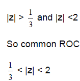
The ROC of z-transform of the discrete time sequence, x(n) so that x(n) is absolutely summable 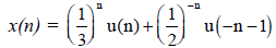

 and
and  in which
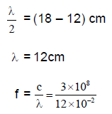
  is band limited to 3 kHZ and
  is band limited to 2KHz, determine the minimum sampling frequency of g(t) where
 = 2kHz
 = 2 × 2
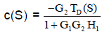
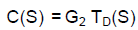
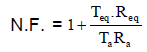
 represents the disturbance in the forward path. The effect of the disturbance can be reduced by
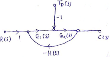
 Increases, disturbance decreases, But gain also decreases. This is not desirable.
 increases, disturbance increases, since noise links with
 increases, disturbance decreases, and gain also decreases. This is desirable.
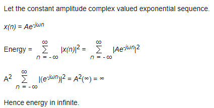
The energy of constant-amplitude complex valued exponential sequence is __________ (where A is the constant amplitude)
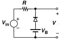
In the given circuit input voltage Vin is 3V and VB is 1.5V. The resistance R is 1.5K. Cut-in voltage of diode is 0.5V. Forward bias resistance is 10Ω. The Voltage V will be ____________
Which of the following is a microwave power amplifier?
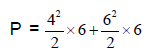
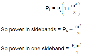
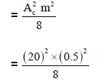
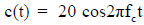 is amplitude modulated by a message signal m (t) =
  .If the modulation index is 0.5, then the power in USB is given by
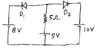
 is ON.
 is Zero.
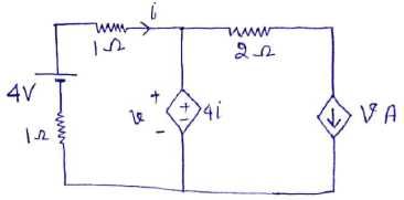
 in the given circuit given
  = 100
= 100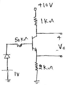
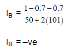
 is negative, so Transistor is in cut-off mode, therefore,
  = 0
= 0 = 10V and
  =0
=0
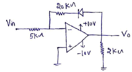
 in the circuit, assume op-amp is ideal.
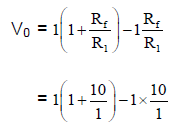
 is at
is at  i.e. –10V and diode is off,and during negative half cycle
  is at
is at  i.e. +10V, so diode is ON and,virtual short-cirucit exist.
 is 2 times of transistor
  then determine the value of
  Assume
  of both the transistors are very large
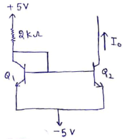
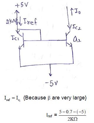
 is two times of
  So
So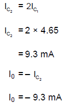

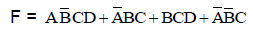
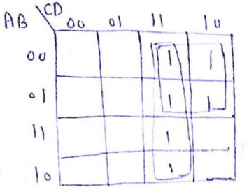
The minimal sum of products form of 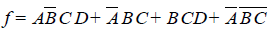 is
is


Important Questions for Practice Test: Electronics Engineering (ECE)- 3
Practice Test: Electronics Engineering (ECE)- 3 MCQs with Answers
Online Tests for Practice Test: Electronics Engineering (ECE)- 3
|
© EduRev
|
Education Revolution
|


|


