Electrical Engineering (EE) Exam  >  Electrical Engineering (EE) Tests  >  GATE Electrical Engineering (EE) Mock Test Series 2025  >  Test: AC Bridges to Electrical & Electronics Measurements - Electrical Engineering (EE) MCQ

Test: AC Bridges to Electrical & Electronics Measurements - Electrical Engineering (EE) MCQ


Test Description

10 Questions MCQ Test GATE Electrical Engineering (EE) Mock Test Series 2025 - Test: AC Bridges to Electrical & Electronics Measurements

Test: AC Bridges to Electrical & Electronics Measurements for Electrical Engineering (EE) 2025 is part of GATE Electrical Engineering (EE) Mock Test Series 2025 preparation. The Test: AC Bridges to Electrical & Electronics Measurements questions and answers have been prepared according to the Electrical Engineering (EE) exam syllabus.The Test: AC Bridges to Electrical & Electronics Measurements MCQs are made for Electrical Engineering (EE) 2025 Exam. Find important definitions, questions, notes, meanings, examples, exercises, MCQs and online tests for Test: AC Bridges to Electrical & Electronics Measurements below.
Solutions of Test: AC Bridges to Electrical & Electronics Measurements questions in English are available as part of our GATE Electrical Engineering (EE) Mock Test Series 2025 for Electrical Engineering (EE) & Test: AC Bridges to Electrical & Electronics Measurements solutions in Hindi for GATE Electrical Engineering (EE) Mock Test Series 2025 course. Download more important topics, notes, lectures and mock test series for Electrical Engineering (EE) Exam by signing up for free. Attempt Test: AC Bridges to Electrical & Electronics Measurements | 10 questions in 30 minutes | Mock test for Electrical Engineering (EE) preparation | Free important questions MCQ to study GATE Electrical Engineering (EE) Mock Test Series 2025 for Electrical Engineering (EE) Exam | Download free PDF with solutions
Test: AC Bridges to Electrical & Electronics Measurements - Question 1

A bridge circuit works at a frequency of 3 kHz. Which detector can be used for detecting the null conditions in the bridge?​

Detailed Solution for Test: AC Bridges to Electrical & Electronics Measurements - Question 1

For 3 kHz frequency headphone (Range - 250 Hz to 4 kHz) and tuned amplifier detector (Range - 10 Hz to 100 kHz) will be used.

Test: AC Bridges to Electrical & Electronics Measurements - Question 2

Inductance comparison bridge uses

Test: AC Bridges to Electrical & Electronics Measurements - Question 3

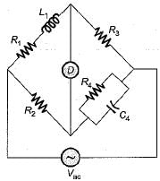
The equations under conditions of balance for a bridge measuring resistance R1, and inductance L1 of a choke coil are

In order to achieve convergence of balance

Detailed Solution for Test: AC Bridges to Electrical & Electronics Measurements - Question 3

The bridge circuit for the given balance condition indicates that of a Maxwell’s inductance capacitance bridge as shown below.

For sliding balance, R4 and Cwill be varied since they are not common in the equations of R1, and L1.
in order to achieve convergence to balance point, R4 and C4 will be varied since they are in the same arm of the bridge.

Test: AC Bridges to Electrical & Electronics Measurements - Question 4

In measurement of resistance by “Carey Foster bridge” no error is introduced due to

Detailed Solution for Test: AC Bridges to Electrical & Electronics Measurements - Question 4

“Carey Foster slide wire bridge” is a special type of bridge circuit which is used for the measurement of medium resistance by comparing with a standard known resistance. This bridge circuit will give no error due to connecting lead resistances, thermoelectric emfs and contact resistances.

Test: AC Bridges to Electrical & Electronics Measurements - Question 5

A capacitance comparison bridge as shown in figure below is used to measure a capacitive impedance at a frequency of 2 kHz. The bridge constants at balance are:

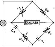
The equivalent series circuit of the unknown impedance will be represented as:

Detailed Solution for Test: AC Bridges to Electrical & Electronics Measurements - Question 5

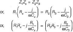
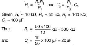
At balance condition,

Separating real and imaginary parts, we have:

Test: AC Bridges to Electrical & Electronics Measurements - Question 6

A Wien bridge circuit consists of the following:

The frequency of the circuit is

Test: AC Bridges to Electrical & Electronics Measurements - Question 7

An ac bridge uses a detector in the form of

Test: AC Bridges to Electrical & Electronics Measurements - Question 8

Maxwell’s bridge is used to measure Q-factor in the range

Detailed Solution for Test: AC Bridges to Electrical & Electronics Measurements - Question 8

Maxwell’s bridge is used to measure Q-factor of medium Q-coils i.e. 1 < Q < 10

Test: AC Bridges to Electrical & Electronics Measurements - Question 9

Anderson bridge is used to measure unknown

Detailed Solution for Test: AC Bridges to Electrical & Electronics Measurements - Question 9

Anderson bridge is used for the measurement of low Q -coils i.e. measurement of low inductance.

Test: AC Bridges to Electrical & Electronics Measurements - Question 10

Hay’s bridge is used to measure an inductance of

Detailed Solution for Test: AC Bridges to Electrical & Electronics Measurements - Question 10

Hay’s bridge is used for the measurement of inductance of high Q-coils (Q > 10).

25 docs|247 tests
Information about Test: AC Bridges to Electrical & Electronics Measurements Page
In this test you can find the Exam questions for Test: AC Bridges to Electrical & Electronics Measurements solved & explained in the simplest way possible. Besides giving Questions and answers for Test: AC Bridges to Electrical & Electronics Measurements, EduRev gives you an ample number of Online tests for practice
Download as PDF