Electrical Engineering (EE) Exam  >  Electrical Engineering (EE) Tests  >  GATE Electrical Engineering (EE) Mock Test Series 2025  >  Test: Compensators - 2 - Electrical Engineering (EE) MCQ

Test: Compensators - 2 - Electrical Engineering (EE) MCQ


Test Description

14 Questions MCQ Test GATE Electrical Engineering (EE) Mock Test Series 2025 - Test: Compensators - 2

Test: Compensators - 2 for Electrical Engineering (EE) 2025 is part of GATE Electrical Engineering (EE) Mock Test Series 2025 preparation. The Test: Compensators - 2 questions and answers have been prepared according to the Electrical Engineering (EE) exam syllabus.The Test: Compensators - 2 MCQs are made for Electrical Engineering (EE) 2025 Exam. Find important definitions, questions, notes, meanings, examples, exercises, MCQs and online tests for Test: Compensators - 2 below.
Solutions of Test: Compensators - 2 questions in English are available as part of our GATE Electrical Engineering (EE) Mock Test Series 2025 for Electrical Engineering (EE) & Test: Compensators - 2 solutions in Hindi for GATE Electrical Engineering (EE) Mock Test Series 2025 course. Download more important topics, notes, lectures and mock test series for Electrical Engineering (EE) Exam by signing up for free. Attempt Test: Compensators - 2 | 14 questions in 45 minutes | Mock test for Electrical Engineering (EE) preparation | Free important questions MCQ to study GATE Electrical Engineering (EE) Mock Test Series 2025 for Electrical Engineering (EE) Exam | Download free PDF with solutions
Test: Compensators - 2 - Question 1

Phase lead compensation

Detailed Solution for Test: Compensators - 2 - Question 1

Lead compensator:
Transfer function:

If it is in the form of  then a < 1

If it is in the form of then a > b
Maximum phase lag frequency: ωm = 1√Ta
Maximum phase lag::


ϕm is positive

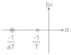
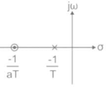
Pole zero plot:

The zero is nearer to the origin.
Filter: It is a high pass filter (HPF)
Effect on the system:

  • Rise time and settling time decreases and Bandwidth increases
  • The transient response becomes faster
  • The steady-state response is not affected
  • Improves the stability
  • The velocity constant is usually increased
  • Helps to increase the system error constant though to a limited extent
  • The slope of the magnitude curve is reduced at the gain crossover frequency, as a result, relative stability improves
  • The margin of stability of a system (phase margin) increased
Test: Compensators - 2 - Question 2

Direction: The following item consists of two statements, one labelled as ‘Statement (I)’ and the other as ‘Statement (II)’. Examine these two statements carefully and select the answers to these items using the code given below:

Statement I: For type-II or higher systems, lead compensator may be used.
Statement II: Lead compensator increases the margin of stability.

Detailed Solution for Test: Compensators - 2 - Question 2

In general, there are two situations in which compensation is required.

  • In the first case, the system is absolutely unstable, and the compensation is required to stabilize it as well as to achieve a specified performance.
  • In the second case, the system is stable, but the compensation is required to obtain the desired performance.
     

The systems which are of type-2 or higher are usually absolutely unstable. For type-2 or higher systems, only the lead compensator is required because only the lead compensator improves the margin of stability.
Both Statement I and Statement II are individually true and Statement II is the correct explanation of Statement I
Note: In type-1 and type-0 systems, stable operation is always possible if the gain is sufficiently reduced. In such cases, any of the three compensators, lead, lag, lag-lead may be used to obtain the desired performance.

Test: Compensators - 2 - Question 3

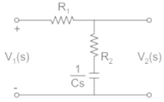
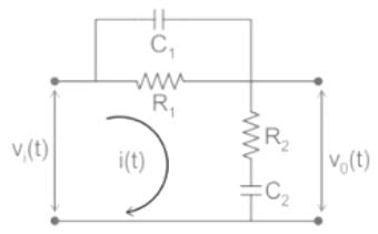
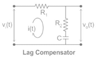
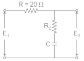
For the following network to work as lag compensator, the value of R2 would be
Detailed Solution for Test: Compensators - 2 - Question 3

Lead compensator:
Transfer function:

If it is in the form of  then a < 1

If it is in the form of then a > b
Maximum phase lag frequency: ωm = 1√Ta
Maximum phase lag::


ϕm is positive

Pole zero plot:

The pole is nearer to the origin.
Filter: It is a low pass filter (LPF)
Effect on the system:

  • Rise time and settling time increases and Bandwidth decreases
  • The transient response becomes slower
  • The steady-state response is improved
  • Stability decreases

Application:
The equivalent Laplace transform network for the given network is,

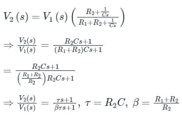
By applying voltage division,
The above system to be lag compensator, β > 1


⇒ R1 > 0
Therefore, at any value of R2 the given system acts as lag compensator.

Test: Compensators - 2 - Question 4

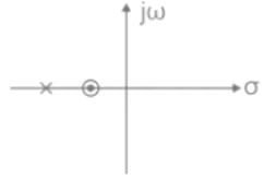
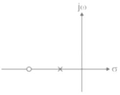
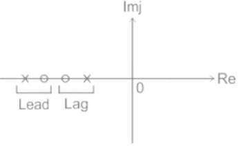
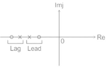
Which of the following can be the pole-zero configuration of a phase-lag controller (lag compensator)?

Detailed Solution for Test: Compensators - 2 - Question 4

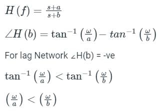
Let H(f) be TF of phase-lag controller


b < a
Pole is near to j ω axis than zero 

Test: Compensators - 2 - Question 5

Which of the following statements is incorrect?

Detailed Solution for Test: Compensators - 2 - Question 5

Concept:

  • Lag Compensation adds a pole at origin (or for low frequencies).
  • Lag Compensation to reduce the steady-state error of the system.
  • An unstable system is a system that has at least one pole at the right side of the s-plane.
  • So, even if we add a lag compensator to an unstable system, it will remain unstable.
     

Explanation:
If an already unstable system has a CLTP = 

After using a lag compensator the CLTP = 
The system is still unstable.

Test: Compensators - 2 - Question 6

The Transfer Function of lead and lag compensators have _____ and ______ phase angles respectively which the system ______ and ______ respectively.

Detailed Solution for Test: Compensators - 2 - Question 6

Concept:
We know:
Hc(s) = s+as+b;
when α = zero/pole = α/b is greater than 1 i.e., α > 1 then it is lag compensator.
else when α < 1, then it is lead compensator.
Calculation:
For lead compensator: Hc(s) = s+a/s+b

ϕ = tan−1(ω/1) − tan−1(ω/2)
i.e., phase angle will be positive for ω > 0
similarly, for lag compensator:  Hc(s) = s+2/s+1

ϕ = tan−1(ω/2) −tan−1(ω)
i.e. phase angle is negative for ω > 0.
Now,
For lead compensator, gain crossover frequency (ωgc) increase which causes an increase in B.W. and hence the speed of the system improves.
For lag compensator; Gain crossover frequency (ωpc) decreases which causes decreases in B.W. and hence speed of the system decreases.

Test: Compensators - 2 - Question 7

Which of the following is NOT the disadvantage of lag compensator in a control system?

Detailed Solution for Test: Compensators - 2 - Question 7

Advantages of Lag Compensator:

  • A phase lag network offers high gain at low frequency. Thus, it performs the function of a low pass filter.
  • The introduction of this network increases the steady-state performance of the system.
  • The lag network offers a reduction in bandwidth and this provides longer rise time and settling time and so the transient response.
  • The angular contribution of the pole is more than that of the compensator zero because the pole dominates the zero in the lag compensator.

 
Advantages of Lead Compensator:

  • It improves the damping of the overall system.
  • The enhanced damping of the system supports less overshoot along with less rise time and settling time. Therefore, the transient response gets improved.
  • The addition of a lead network improves the phase margin.
  • A system with a lead network provides a quick response as it increases bandwidth thereby providing a faster response.
  • Lead networks do not disturb the steady-state error of the system.
  • It maximizes the velocity constant of the system.
Test: Compensators - 2 - Question 8

The transfer function represents a

Detailed Solution for Test: Compensators - 2 - Question 8

Concept:
Lag compensator:
Transfer function:
If it is in the form of then a < 1
If it is in the form ofthen a > b
Maximum phase lag frequency: 
 ωm = 1/T√a
Maximum phase lag: ϕm = sin−1(α−1/α+1)
ϕm is negative
Pole zero plot:

The pole is nearer to the origin.
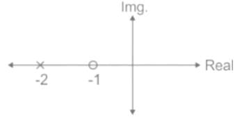
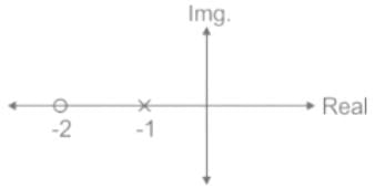
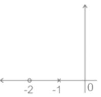
Given:

Zero = -2
Pole = -1
Analysis:
The pole-zero plot of T(s) is as shown:

Since the pole is closer to the origin than zero.
It is a lag compensator.

Test: Compensators - 2 - Question 9

If the transfer function of a compensator is represented as:


How much maximum phase shift can it add to the system?

Detailed Solution for Test: Compensators - 2 - Question 9

Concept:
The standard phase lead compensating network is given as:

Maximum phase Occurs at
ωm = 1/T√α
Maximum phase (ϕm)
sinϕm = 1−α/1+α

Calculation:
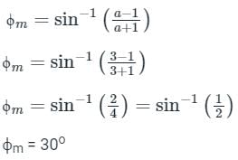
Given:

a = 3 and T = 0.1
∵ a > 1 
It is a Lead compensator.
Maximum phase lead is given as:

Test: Compensators - 2 - Question 10

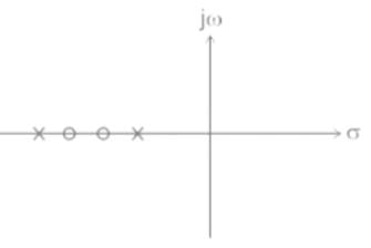
The pole-zero plot shown below represents a

Detailed Solution for Test: Compensators - 2 - Question 10

Concept:
The speed of response and, the steady-state error can be simultaneously improved if both phase-lag and phase-lead compensation networks are used. However, instead of using two separate lag and lead networks, a single network combining both can be used.

Lag-lead compensator:

In the lag-lead compensator network, the lag compensator is nearer to the origin.

Lead-lag compensator:


In the lead-lag compensator network, the lead compensator is nearer to the origin.

Test: Compensators - 2 - Question 11

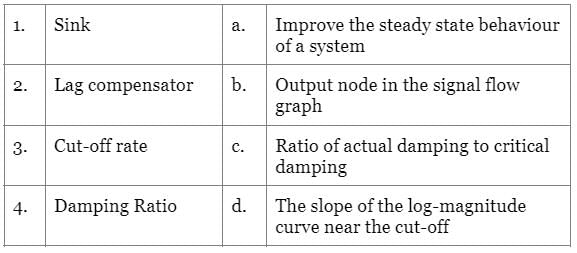
Match the following :-

Detailed Solution for Test: Compensators - 2 - Question 11

Sink node:

  • A local sink is a node of a directed graph with no exiting edges, also called a terminal.
  • It is the output node in the signal flow graph. It is a node, which has only incoming branches.

Lag Compensator: 

  • Phase lag network offers high gain at low frequency.
  • Thus, it performs the function of a low pass filter.
  • The introduction of this network increases the steady-state performance of the system.

Damping Ratio:

  • The damping ratio gives the level of damping in the control system related to critical damping.
  • The damping ratio is defined as the ratio of actual damping to the critical damping of the system.
  • It is the ratio of the damping coefficient of a differential equation of a system to the damping coefficient of critical damping.
  • ζ = actual damping / critical damping

Cut-off rate: It is the slope of the log-magnitude curve near the cut-­off region of the Bode-plot.

Test: Compensators - 2 - Question 12

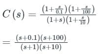
The transfer function C(s) of a compensator is given below.

The frequency range in which the phase (lead) introduced by the compensator reaches the maximum is

Detailed Solution for Test: Compensators - 2 - Question 12


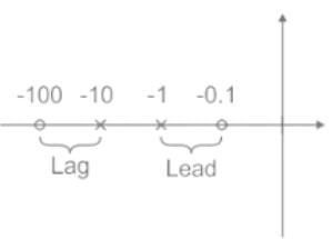
Pole zero diagram of the above transfer function is

It represents a standard lead lag compensator. For a lead lag compensator, maximum lead occurs at initial frequency.
So, maximum lead occurs at 0.1 < ω < 1.

Test: Compensators - 2 - Question 13

In the phase lead compensation network, the phase of ______ leads the phase of ______.

Detailed Solution for Test: Compensators - 2 - Question 13

Lead compensator:
Transfer function:

If it is in the form of  then a < 1

If it is in the form of then a > b
In the frequency domain, 

Phase angle, ∠G (jω) = tan−1ωαT − tan−1ωT

ϕ = tan-1 ωaT – tan-1 ωT
As a > 1 always (from the definition), ϕ is positive
Hence, it is clear that the phase of output voltage leads the phase of the input voltage.

Test: Compensators - 2 - Question 14

If r = 1 in the G(s) =  then the compensator can give the minimum phase at a frequency of

Detailed Solution for Test: Compensators - 2 - Question 14

Concept:
Lead and Lag compensators:
Gc(s) = (1 + aTs) / (1 + Ts) where a and T > 0, a > 1 (lead) & a < 1 (lag)
∠Gc(s) = ϕ = tan-1 ωaT – tan-1 ωT
ωm is the geometric mean of the two corner frequencies 1/T and 1/aT
ωm = 1/T√α

Calculations:
Given Gc(s) = 
r = 1
By substituting r value we get Gc(s) = 
Here T = 1 and a = 0.1

25 docs|247 tests
Information about Test: Compensators - 2 Page
In this test you can find the Exam questions for Test: Compensators - 2 solved & explained in the simplest way possible. Besides giving Questions and answers for Test: Compensators - 2, EduRev gives you an ample number of Online tests for practice
Download as PDF