Test: Thyristor Commutation Techniques - Electrical Engineering (EE) MCQ
10 Questions MCQ Test - Test: Thyristor Commutation Techniques

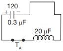
A commutation circuit shown in figure
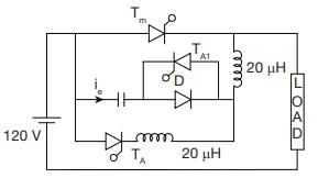
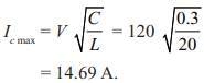
What will be the maximum possible value of current through auxiliary thyristor
TA when C = 0.3 mF L = 20 μH
What will be the maximum possible value of current through auxiliary thyristor
TA when C = 0.3 mF L = 20 μH

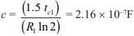
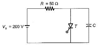
A voltage commutation circuit shown in figure. If turn off time of SCR is 10 μs and safety margin of 1.5. What will be the minimum value of capacitor required for commutation.
Turn-on time (ton) of an SCR is related to its turn-off time (toff) in which of the following way?
Assertion (A) : It is necessary to keep the thyristor reverse biased for a finite period before a forward anode voltage can be reapplied.
Reason (R) : Once the SCR starts conducting an appreciable forward current, the gate has no control on it and the device can be brought back to the blocking state only by reducing the forward current level below that of the holding current.
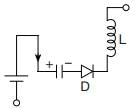
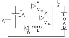
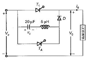
In a class D commutation as, shown in figure. L = 1 μH & C = 2 μF. For a constant load current of 100 A, calculate circuit turn off time for auxiliary thyristor


Consider the following statements associated with various commutation techniques of a thyristor:
1. In forced commutation, the commutating components L and C carry load current continuously.
2. Forced commutation is usually employed in dc choppers.
3. In load commutation, L and Care connected in parallel with the load or C in series with the load.
4. Load commutation is employed in series inverters.
5. In class-C commutation, the main thyristor that is to be commutated is connected in parallel with the load.
Which of the statements given above are correct?
For the class-B commutation circuit shown below, the initial voltage across capacitor is 230 volt. For a constant load current of 300 A, the conduction time for the auxiliary thyristor is approximately equal to
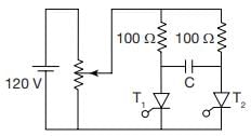
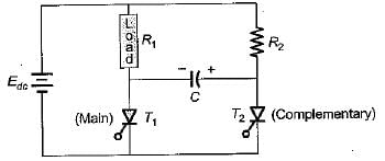
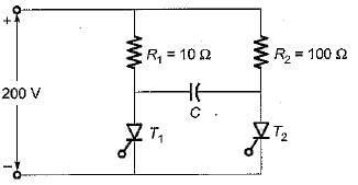
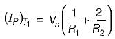
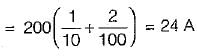
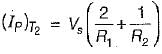
For the circuit shown below, the peak value of the current through thyristors T1 and T2 are
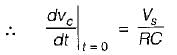
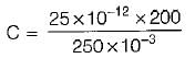
The SCR in the circuit shown below is forced commutated by a circuitry not shown in the figure. The SCR has minimum charging current of 5 mA to turn it on and its junction capacitance is 25 pF.
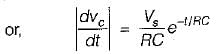
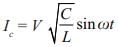
 ...(i)
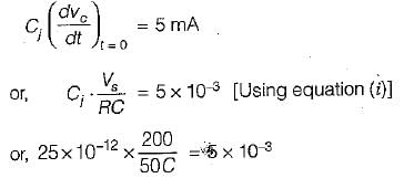
Important Questions for Thyristor Commutation Techniques
Thyristor Commutation Techniques MCQs with Answers
Online Tests for Thyristor Commutation Techniques
|
© EduRev
|
Education Revolution
|


|


