1 Crore+ students have signed up on EduRev. Have you? Download the App |
The signal flow graph given below.
The transfer function=
=
The output of the feedback control system must be a function of:
Explanation: In a feedback control system, the output is determined by a combination of the input signal and the feedback signal. The input signal is the desired output or reference, while the feedback signal is a portion of the actual output that is fed back into the system to compare with the input. This comparison helps the system to adjust its output to minimize the error between the input and the actual output. By considering both the input and feedback signals, the system can continuously adapt and achieve the desired output.
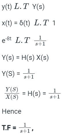
The unit impulse response of a certain system is found to be e-8t. Its transfer function is _______.
The impulse response is defined as the output of an LTI system due to a unit impulse signal input being applied at time t = 0.
y(t) = h(t) x(t) = h(t) δ(t)
where δ(t) is the unit impulse function and h(t) is the unit impulse response of a continuous-time LTI system.
Calculations:-
Given-
y(t) = e-8t
x(t) = δ(t)
For calculating the transfer function convert the time domain response into Laplace or S domain.
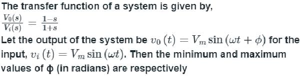
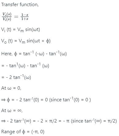
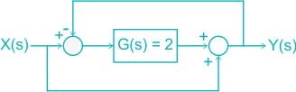
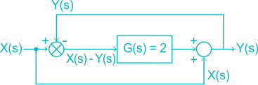
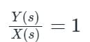
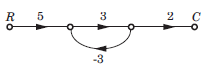
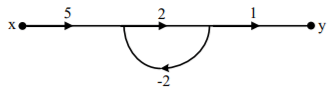
For the system shown in the figure, Y(s)/X(s) = _________. (Answer in integer )
The circuit is redrawn as shown:
[X(s) – Y(s)] G(s) + X(s) = Y(s)
Given G(s) = 2
(X(s) – Y(s)) 2 + X(s) = Y(s)
= 2 X(s) + X(s) = Y(s) + 2Y(s)
= 3 X(s) = 3 Y(s)
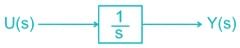
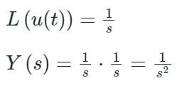
Assuming zero initial condition, the response y(t) of the system given below to a unit step input u(t) is
Laplace transform of u(t) is given by
Taking Inverse Laplace transform
y(t) = t.u(t)
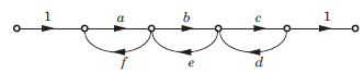
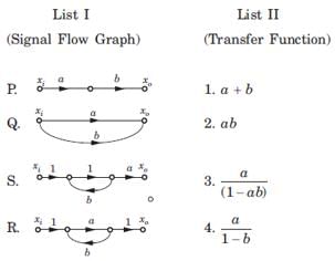
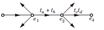
The sum of the gains of the feedback paths in the signal flow graph shown in fig. is
So, af, be and cd are the only valid feedback paths. The sum of the gains of the feedback paths in the signal flow graph is af + be + cd.
A control system whose step response is -0.5(1+e-2t) is cascaded to another control block whose impulse response is e-t. What is the transfer function of the cascaded combination?
Let's first find the transfer function of the first control system. We know that the step response is given by: y(t) = -0.5(1+e^(-2t))
Taking the Laplace transform of both sides, we get: Y(s) = -0.5(1/s + 1/(s+2))
The transfer function of the first control system is therefore: G1(s) = Y(s)/U(s) = -0.5/(s(s+2))
Now let's find the transfer function of the second control block. We know that the impulse response is given by: h(t) = e^(-t)
Taking the Laplace transform of both sides, we get: H(s) = 1/(s+1)
The transfer function of the second control system is therefore: G2(s) = H(s)/U(s) = 1/(s+1)
The transfer function of the cascaded combination is given by the product of the individual transfer functions: G(s) = G1(s) * G2(s) = [-0.5/(s(s+2))] * [1/(s+1)] = -0.5/(s(s+2)(s+1))
Therefore, the correct answer is: 1/(s+2)(s+1).
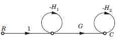
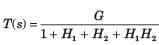
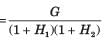
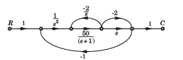
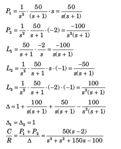
The overall transfer function C/R of the system shown in fig. will be:
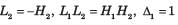
For the signal flow graph shown in fig. an equivalent graph is
While writing the transfer function of this signal flow graph,
e2= tae1 + tbe1 = (ta+ tb) e1
Then, signal flow graph will lokk like this:
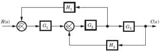
The block diagram of a system is shown in fig. The closed loop transfer function of this system is
Consider the block diagram as SFG. There are two feedback loop -G1G2H1 and -G2G3H2 and one forward path G1G2 G3 . So (D) is correct option.
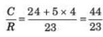
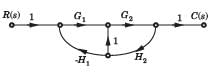
For the system shown in fig. transfer function C(s) R(s) is
Consider the block diagram as a SFG. Two forward path G1G2 and G3 and three loops -G1G2 H2, -G2H1, -G3 H2
There are no nontouching loop. So (B) is correct.
In the signal flow graph shown in fig. the transfer function is
P1 = 5 x 3 x 2 = 30, Δ = 1 - (3x - 3) = 10
Δ1 = 1,
In the signal flow graph shown in fig. the gain C/R is
P1 = 2 x 3 x 4 = 24 , P2 = 1 x 5 x 1 = 5
L1 = -2, L2 = -3, L3 = -4, L4 = -5,
L1L3 = 8, Δ = 1 -(-2 - 3 - 4 - 5) + 8 = 23, Δ1 = 1, Δ2 = 1 - (-3) = 4,
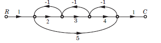
The gain C(s)/R(s) of the signal flow graph shown in fig.
X1 = 1 - H1
X2 = (G1 + G3) X1 - X3H1
X3 = X2G2 + G4
The negative feedback closed-loop system was subjected to 15V. The system has a forward gain of 2 and a feedback gain of 0.5. Determine the output voltage and the error voltage.
Given:
G(s) = 2
H(s) = 0.5 and R(s) = 10V
Output voltage:
= (2/1 + 2 x 0.5) x 15 = 15V
Error voltage:
= (1/1 + 2 x 0.5) x 15 = 7.5V
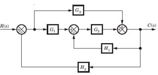
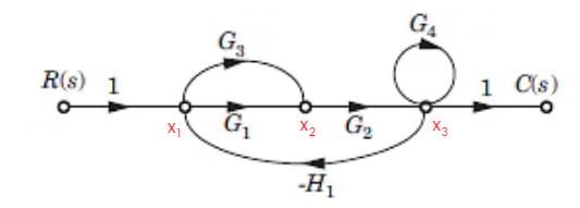
For the block diagram shown in fig. transfer function C(s)/R(s) is
Four loops -G1G4, -G1G2G5, -G1,G2G5G7 and -G1G2G3G3G7.
There is no nontouching loop. So (B) is correct.
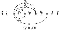
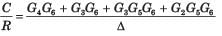
For the block diagram shown in fig. the numerator of transfer function is
SFG
P1 = G2G5G6 , P2 = G3G5G6, P3 = G3G6 , P4 = G4G6
If any path is deleted, there would not be any loop.
Hence Δ1 = Δ2 = Δ3 = Δ4 = 1
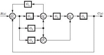
For the block diagram shown in fig. the transfer function C(s)/R(s) is
Transfer function
PK = 5 x 2 x 1 = 10
ΔK = 1
Δ = 1 - (-4) = 5
= 2
22 docs|274 tests
|
22 docs|274 tests
|