Electrical Engineering (EE) Exam  >  Electrical Engineering (EE) Tests  >  Analog and Digital Electronics  >  Test: Sample & Hold Circuits - Electrical Engineering (EE) MCQ

Test: Sample & Hold Circuits - Electrical Engineering (EE) MCQ


Test Description

10 Questions MCQ Test Analog and Digital Electronics - Test: Sample & Hold Circuits

Test: Sample & Hold Circuits for Electrical Engineering (EE) 2024 is part of Analog and Digital Electronics preparation. The Test: Sample & Hold Circuits questions and answers have been prepared according to the Electrical Engineering (EE) exam syllabus.The Test: Sample & Hold Circuits MCQs are made for Electrical Engineering (EE) 2024 Exam. Find important definitions, questions, notes, meanings, examples, exercises, MCQs and online tests for Test: Sample & Hold Circuits below.
Solutions of Test: Sample & Hold Circuits questions in English are available as part of our Analog and Digital Electronics for Electrical Engineering (EE) & Test: Sample & Hold Circuits solutions in Hindi for Analog and Digital Electronics course. Download more important topics, notes, lectures and mock test series for Electrical Engineering (EE) Exam by signing up for free. Attempt Test: Sample & Hold Circuits | 10 questions in 30 minutes | Mock test for Electrical Engineering (EE) preparation | Free important questions MCQ to study Analog and Digital Electronics for Electrical Engineering (EE) Exam | Download free PDF with solutions
Test: Sample & Hold Circuits - Question 1

A good Sample and Hold circuit should have

  1. High input impedance
  2. High output impedance
  3. Low input impedance 
  4. Low output impedance

Detailed Solution for Test: Sample & Hold Circuits - Question 1

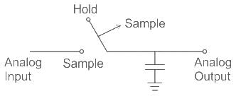
Sample and Hold (S/H) circuit:

It is used with an analog to digital converter to sample the input analog signal and hold the sample signal.

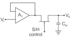
Circuit:- 

Properties:
1. A S/H Circuit should have high input impedance and low output impedance because due to high input impedance loading effect [It is the degree to which a measurement instrument impact electrical properties (Voltage, Current, resistance) of a Circuit] is less and Circuit performance is better.

Conclusions:
for better circuit performance input impedance should be high and output impedance should be low.

Option 4 correct choice.

Test: Sample & Hold Circuits - Question 2

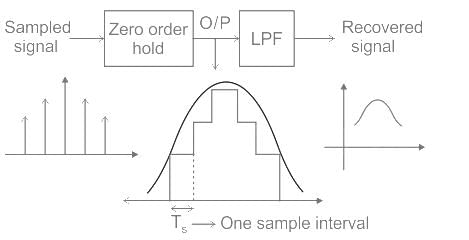
Figure shows 4 block diagram of a system to recover a sampled signal shown as input.

Blocks A and B can be respectively :

Detailed Solution for Test: Sample & Hold Circuits - Question 2

Zero-order hold circuit:

It is a mathematical model of two practical signal Reconstruction done by convention Digital to Analog converter (DAC).
By holding each sample value for one sample interval it converts the discrete signal into an analog signal.

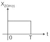
Important Points

Zero-order function 

1 Crore+ students have signed up on EduRev. Have you? Download the App
Test: Sample & Hold Circuits - Question 3

Sample-and-hold circuits in ADCs are designed to:

Detailed Solution for Test: Sample & Hold Circuits - Question 3

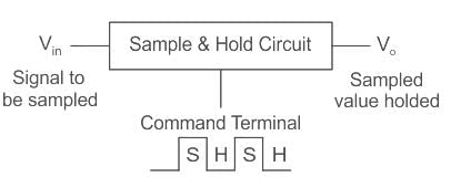
Sample & Hold Circuit is used to sample the given input signal and to hold the sampled value.
Sample and hold circuit is used to sample an analog signal for a short interval of time in the range of 1 to 10 µS and to hold on to its last sampled value, until the input signal is sampled again.
The holding period may be from a few milliseconds to several seconds.

Applications of Sample & Hold circuits:

  • Out of different ADCs, successive approximation type ADC uses an S/H circuit, where the signal is to be held constant while A to D conversion is taking place.
  • They are also used in DACs for the same purpose.
  • It is used in analog demultiplexing in data distribution and in analog delay lines.
  • In general, S/H circuits are used in all applications where it is necessary to stabilize the analog signal for further processing.
Test: Sample & Hold Circuits - Question 4

For a given sample-and-hold circuit, if the value of the hold capacitor is increased, then

Detailed Solution for Test: Sample & Hold Circuits - Question 4

Concepts:

Generally, a sample & hold circuit is designed using an opamp. The given circuit shows the general implementation:

Sample & Hold circuit capacitor CH is charged by the Amplifier A1.
The maximum output current of the opamp is given as:

 
Droop rate  when V0 is the voltage at the steady state.
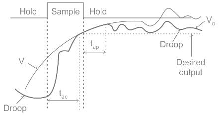
The acquisition time (tac) is depicted in the following figure:

Analylsis:


If C­H increases then ‘t’ which is the acquiring time must also increase to maintain the relationship.
Also, capacitor discharging time constant TC(discharge) is proportional to capacitance i.e.

So if CH increases then capacitor voltage decreases slowly because of discharging time constant, this means droop rate decreases.

Test: Sample & Hold Circuits - Question 5

Increase the order of data hold will

Detailed Solution for Test: Sample & Hold Circuits - Question 5

Data Hold
Data hold is a process of generating a continuous-time signal h(t) from a discrete-time sequence x(kT).
The signal h(t) during the time interval kT ≤ t ≤ (k + 1)T may be approximated by a polynomial in τ as follows:
h(kT + τ ) = anτn + an−1τn−1 + ··· + a1τ + a0
Where 0 ≤ τ ≤ T

Note: h(kT) = x(kT)
h(kT + τ ) = anτn + an−1τn−1 + ··· + a1τ + x(kT)
If the data hold circuit is an nth-order polynomial extrapolator, it is called an nth-order hold. It uses the past n + 1 discrete data x((k − n)T), x((k − n + 1)T), ··· , x(kT) to generate h(kT + τ ).

Conclusion:
As the order of the data hold increases the circuit order(n) also increases which leads to the further increase in the time delay because it has to use past n + 1 samples.
Option 3 is correct.

Test: Sample & Hold Circuits - Question 6

A signal channel signal acquisition system with 0-10 V range consist of a sample and hold circuit with worst case drop rate of 100 μV/ms and 10 bit ADC. The maximum conversion time for the ADC is

Detailed Solution for Test: Sample & Hold Circuits - Question 6

In an ADC along with sample and hold circuit, for avoiding error at the output, the voltage of the capacitor should be not dropped by more than ± Δ/2

Δ/2 = 4.88 × 10³ V
Maximum conversation time for the ADC is


= 48.87 msec ≈ 49 msec

Test: Sample & Hold Circuits - Question 7

When a time-varying signal has to be digitized using an ADC, which of the following is necessary to use before digitization?

Detailed Solution for Test: Sample & Hold Circuits - Question 7

Sample and Hold circuit:
It samples the incoming analog signal and holds this sample values for a certain instant of time.
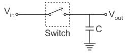
In the basic circuit diagram, an analog switch and a capacitor is used to perform the work.

In this circuit, the switch can be either BJT, MOSFET, etc.
When the switch is closed by the applied input signal, the capacitor starts charging and holds the sampled value and the sampling interval is the same as the charging duration of the capacitor.
The capacitor holds the sampled value for half interval and changes its value in another half interval of time.

Application of sample and hold circuit

Analog to digital converter

  • Signal processing
  • Filter design
  • Oscilloscope

Explanation:
When a time varying signal has to be digitized using an ADC, sample and hold circuit is necessary to use before digitation. Because sample and hold circuit take sample at particular instant.

Test: Sample & Hold Circuits - Question 8

What is the main function of (A/D) or ADC converter?

Detailed Solution for Test: Sample & Hold Circuits - Question 8

The electronic device that performs this conversion from an analog signal to a digital sequence is called an analog-to-digital (A/D) converter (ADC).

Test: Sample & Hold Circuits - Question 9

The time required to complete the conversion of Analog to Digital is ________ the duration of the hold mode of S/H.

Detailed Solution for Test: Sample & Hold Circuits - Question 9

The A/D converter begins the conversion after it receives a convert command. The time required to complete the conversion should be less than the duration of the hold mode of S/H.

Test: Sample & Hold Circuits - Question 10

In A/D converter, what is the time relation between sampling period T and the duration of the sample mode and the hold mode?

Detailed Solution for Test: Sample & Hold Circuits - Question 10

The A/D converter begins the conversion after it receives a convert command. The sampling period T should be larger than the duration of the sample mode and the hold mode.

137 videos|143 docs|71 tests
Information about Test: Sample & Hold Circuits Page
In this test you can find the Exam questions for Test: Sample & Hold Circuits solved & explained in the simplest way possible. Besides giving Questions and answers for Test: Sample & Hold Circuits, EduRev gives you an ample number of Online tests for practice

Top Courses for Electrical Engineering (EE)

137 videos|143 docs|71 tests
Download as PDF

Top Courses for Electrical Engineering (EE)