Electrical Engineering (EE) Exam  >  Electrical Engineering (EE) Tests  >  Analog and Digital Electronics  >  Test: Sequential Circuits - 2 - Electrical Engineering (EE) MCQ

Test: Sequential Circuits - 2 - Electrical Engineering (EE) MCQ


Test Description

15 Questions MCQ Test Analog and Digital Electronics - Test: Sequential Circuits - 2

Test: Sequential Circuits - 2 for Electrical Engineering (EE) 2024 is part of Analog and Digital Electronics preparation. The Test: Sequential Circuits - 2 questions and answers have been prepared according to the Electrical Engineering (EE) exam syllabus.The Test: Sequential Circuits - 2 MCQs are made for Electrical Engineering (EE) 2024 Exam. Find important definitions, questions, notes, meanings, examples, exercises, MCQs and online tests for Test: Sequential Circuits - 2 below.
Solutions of Test: Sequential Circuits - 2 questions in English are available as part of our Analog and Digital Electronics for Electrical Engineering (EE) & Test: Sequential Circuits - 2 solutions in Hindi for Analog and Digital Electronics course. Download more important topics, notes, lectures and mock test series for Electrical Engineering (EE) Exam by signing up for free. Attempt Test: Sequential Circuits - 2 | 15 questions in 45 minutes | Mock test for Electrical Engineering (EE) preparation | Free important questions MCQ to study Analog and Digital Electronics for Electrical Engineering (EE) Exam | Download free PDF with solutions
Test: Sequential Circuits - 2 - Question 1

In a J-K flip-flop, if J = K̅, then it acts as a/an:

Detailed Solution for Test: Sequential Circuits - 2 - Question 1

D flip flop:

D flip flop has only one input terminal. The output of the D flip flop will be the same as the input. Hence, it is used in delay circuits.

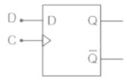
The circuit is as shown below:

Logic symbol:

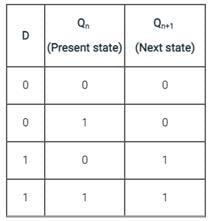
Truth table:

Characteristic equation: Qn+1 = D

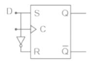
The D flip flop may be obtained from an S-R flip flop by just putting one inverter between the S and R as shown in the figure below.

S = R̅

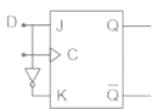
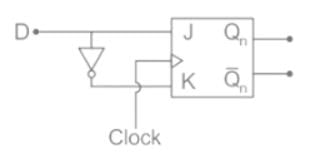
The D flip flop may be obtained from a J-K flip flop by just putting one inverter between the J and K as shown in the figure below.

K = J̅

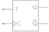
T flip flop:

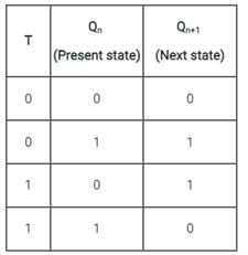
T flip flop has only one input terminal. The output of the T flip flop will be toggled when the input is high on every new clock pulse. The output will be the same as the previous state when the input is low.

The circuit is as shown below:

Logic symbol:

Truth table:

Characteristic equation: Qn+1 = TQ̅­+ T̅Qn

The T flip flop may be obtained from a J-K flip flop by making both the inputs are the same i.e. J = K.

Test: Sequential Circuits - 2 - Question 2

Race-around condition occurs in

Detailed Solution for Test: Sequential Circuits - 2 - Question 2

Race around condition:

For JK flip-flop if J, K, and Clock are equal to 1 the state of flip-flop keeps on toggling which leads to uncertainty in determining the output of the flip-flop. This problem is called Race around the condition.

This can be eliminated by using the following methods:

  • Increasing the delay of flip-flop
  • Use of edge-triggered flip-flop
  • Use of master-slave JK flip flop

The Master-slave configuration is used in a flipflop to eliminate the race around condition but not to store two bits of information.

1 Crore+ students have signed up on EduRev. Have you? Download the App
Test: Sequential Circuits - 2 - Question 3

A pulse train with a frequency of 1 MHz is counted using a mod-1024 ripple counter built with J-K flip-flops. For proper operation of the counter the maximum permissible propagation delay per flip-flop stage is

Detailed Solution for Test: Sequential Circuits - 2 - Question 3

Concept:

If we pass the input signal to a single T-flip flop, we will get half of the frequency at the output.


Similarly, when we pass the input signal into an n-bit flip flop counter, the output frequency (fout) will be:

Calculation:

Given is a mod-1024 ripple counter which means that it can count 1024 states.

To count 1024 number of flipflop required is:

1024 = 2n

n = 10 flip-flops

tpdff = Propagation delay of flip flops

tpdff = 1/f

tpdff = 10-6 sec.

Propagation delay per flipflop =

= 100 nsec

Test: Sequential Circuits - 2 - Question 4

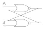
Identify the following sequential component.

Detailed Solution for Test: Sequential Circuits - 2 - Question 4

Explanation:

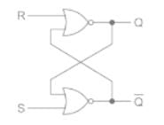
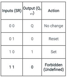
The given sequential component is of RS Flip Flop.

Here A = R and B = S

The truth table for the circuit is shown:

Important Points
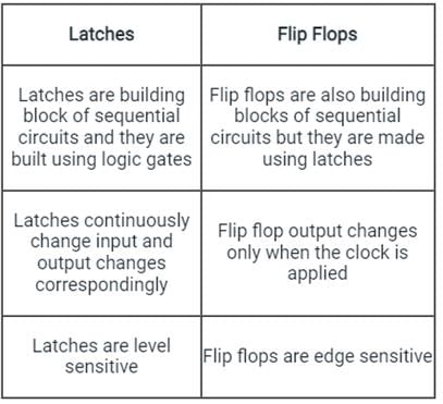
The difference between latches and flip flops is shown

Test: Sequential Circuits - 2 - Question 5

Three T flip flops are connected to form a counter. The maximum states possible for the counter will be:

Detailed Solution for Test: Sequential Circuits - 2 - Question 5

Concept:

For a counter with ‘n’ flip flops:

  • The total number of states = 2n (0 to 2n – 1)
  • The largest number that can be stored in the counter = 2n – 1

To construct a counter with any MOD number, the minimum number flip flops required must satisfy:

Modulus ≤ 2n

Where n is the number of flip-flops and is the minimum value satisfying the above condition.

Calculation:

The total number of states required when n = 3:

23  ≥  8

The states will vary from (0 to 7)

So the maximum states possible for the counter will be 8.

Test: Sequential Circuits - 2 - Question 6

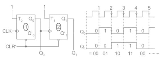
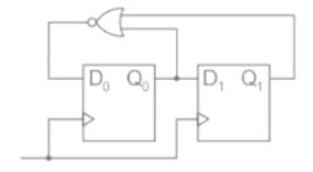
For the circuit shown, the counter state (Q1Q0) follows the sequence
Detailed Solution for Test: Sequential Circuits - 2 - Question 6

Concept:

D-flipflop is a flipflop that produces a delay of exactly one cycle to the CLK.


The characteristic equation of a D flip flop is:

Qn+1 = D

It is also known as ‘’Transparent latch” because Qn+1 = D

Application:

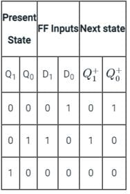
From given sequential circuit:

D0 = Q1 + Q0 and D1 = Q0

Now,

So, counts state (Q1 Q0) follows the sequence:

00 → 01 → 10 → 00 → 01 ….

Test: Sequential Circuits - 2 - Question 7

An eight-bit binary ripple UP counter with a modulus of 256 is holding the count 01111111. What will be the count after 135 clock pulses?

Detailed Solution for Test: Sequential Circuits - 2 - Question 7

01111111 → 127

After 135 clock cycles, we will get

127 + 135 = 262

∴ The total number of clock pulses will be 262

As the modulus is 256,

After 256 clock pulses, the sequence will repeat.

262 = 256 + 6

∴ 00 00 00 00

257 → 00 00 00 01

258 → 00 00 00 10

259 → 00 00 00 11

260 → 00 00 01 00

261 → 00 00 01 01

262 → 00 00 01 10

Test: Sequential Circuits - 2 - Question 8

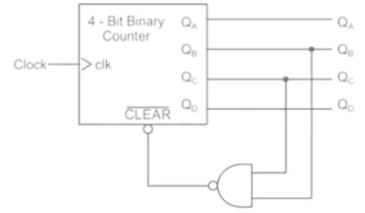
A mod–n counter using a synchronous binary up–counter with synchronous clear input is shown in the figure. The value of n is_________.    

(Important - Enter only the numerical value in the answer)

Detailed Solution for Test: Sequential Circuits - 2 - Question 8

Concept:

CLR: It is an active low signal. It is activated when CLR = 0 and it resets the FF.

CLR: It is an active high signal. It is activated when CLR = 1 and it Resets the FF.

Synchronous: Synchronous clear is synchronized with the clock. It waits for a clock pulse to Reset FF output.

Asynchronous: Asynchronous Clear is not synchronized with the clock. It does not wait for a clock pulse to Reset FF output.

Application:

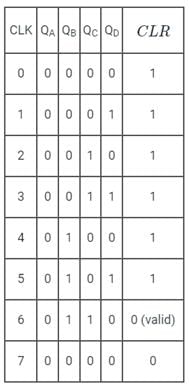
From given sequential circuit:

CLR = QB ⋅ QC

When both QB & QC equal to 1 then CLR = 0. Otherwise CLR = 1

Now,

Since it is given that the counter have synchronous clear input, the output of the counter will reset at the 7th clock pulse.

∴ The mod of the counter, n = 7

Test: Sequential Circuits - 2 - Question 9

A sequence detector is designed to detect precisely 3 digital inputs, with overlapping sequences detectable. For the sequence (1,0,1) and input data (1,1,0,1,0,0,1,1,0,1,0,1,1,0), what is the output of this detector?

Detailed Solution for Test: Sequential Circuits - 2 - Question 9

sequence detector is a sequential circuit that outputs 1 when a particular pattern of bits sequentially arrives at its data input.

Given input data = 1,1,0,1,0,0,1,1,0,1,0,1,1,0

Overlapping sequences detectable.

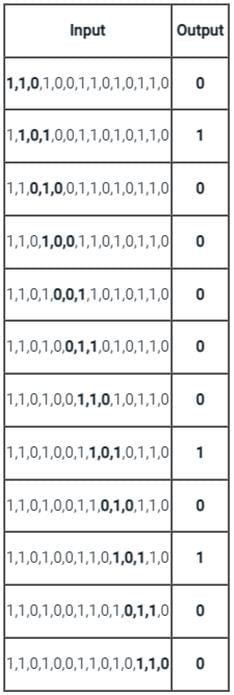
The below table shows the output for each sequence:

The output = 0,1,0,0,0,0,0,1,0,1,0,0

Test: Sequential Circuits - 2 - Question 10

Which of the following is not a sequential circuit?

Detailed Solution for Test: Sequential Circuits - 2 - Question 10
  • Combinational logic is a type of digital logic that is implemented by Boolean circuits, where the output is a pure function of the present input only.
  • Sequential logic is a type of digital logic in which the output depends not only on the present input but also on the history of the output.
  • Sequential logic has memory while combinational logic does not.
  • Flip-flop, counter, and shift registers are sequential circuits whereas multiplexer, decoder, and encoder act like combinational circuits.
Test: Sequential Circuits - 2 - Question 11

A __________ counter can be implemented using three flipflops.

Detailed Solution for Test: Sequential Circuits - 2 - Question 11

Concept:

For a counter with ‘n’ flip flops:

  • The total number of states = 2n (0 to 2n – 1)
  • The largest number that can be stored in the counter = 2n – 1

To construct a counter with any MOD number, the minimum number flip flops required must satisfy:

Modulus ≤ 2n

Where n is the number of flip-flops and is the minimum value satisfying the above condition.

Calculation:

Given: 

n = 3

Modulus ≤ 2n

Modulus ≤ 23

Modulus ≤ 8

The most appropriate answer is option 1 i.e. Mod 6.

Test: Sequential Circuits - 2 - Question 12

If the 5-bit ripple counter and 5-bit synchronous counter are having flip-flops with a propagation delay of 20 ns, the maximum delay in the ripple counter (x) and synchronous counter (y) will be:

Detailed Solution for Test: Sequential Circuits - 2 - Question 12

Concept:

Ripple counter:

In the ripple counter, the clock signal is applied to the LSB flip-flop and the output of the flip-flop acts as the input clock pulse for the next flip-flop.

Hence, as the no. of the flip-flop increases, the delay in the ripple counter also increases.

The maximum delay in the ripple counter is given by:

Td = nTf

Synchronous counter:

In the synchronous counter, all the flip-flops have a common clock signal.

Hence, as the no. of flip-flops increases, the delay in the synchronous counter does not increase.

Td = Tf

Calculation:

Given, n = 5

Tf = 20 ns

For ripple counter:

Td = 5 × 20

Td = 100 ns

For synchronous counter:

Td = 20 ns

*Answer can only contain numeric values
Test: Sequential Circuits - 2 - Question 13

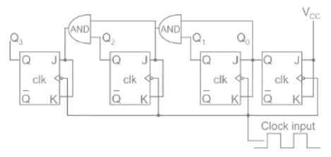
For the following cascaded Counters find the value of X of the mode-X counter.   

(Important - Enter only the numerical value in the answer)


Detailed Solution for Test: Sequential Circuits - 2 - Question 13

Concept:

  • The N-bit ring counter will have total N states/Mods.
  • The N-bit johnson counter will have a total 2N number of states/Mods.
  • The output frequency of a counter is the input frequency divided by the mode number of that counter.

Solution: 

The frequency at node Y is 

Fy = 150kHz/5

= 30 kHz

The frequency at node Z is

Fz = 30kHz/X

here X is the Mod number

then output frequency is given by

 X = 10

Test: Sequential Circuits - 2 - Question 14

In a D flip flop, if the present state is 1, what will be the next state of the output at the complement end?

Detailed Solution for Test: Sequential Circuits - 2 - Question 14

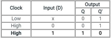
Truth table of D Flip-Flop:

  • The D(Data) is the input state for the D flip-flop.
  • The Q and Q’ represents the Normal output and Complementary or Inverted output states respectively of the flip-flop.
  • According to the table, based on the inputs the output changes its state. But, the important thing to consider is all these can occur only in the presence of the clock signal. 
  • As shown in the truth table of the D flip flop given above, if the present state is '1', then '0' will be the next state of the output at the complement end.

Additional Information

D Flip-flop:

  • D Flip-flops are used as a part of memory storage elements and data processors.
  • The symbol of the D flip-flop is shown below

  • D flip-flops can be built using NAND gate or with NOR gate.
  • Due to their versatility, they are available as IC packages.
  • The major applications of D flip-flops are to introduce delay in timing circuits, as a buffer, and to sample data at specific intervals.
  • D flip-flop is simpler in terms of wiring connection compared to JK flip-flop.
  • Here we are using NAND gates for demonstrating the D flip flop.
  • Whenever the clock signal is LOW, the input is never going to affect the output state.
  • The clock has to be high for the inputs to get active.
  • Thus, D flip-flop is a controlled Bi-stable latch where the clock signal is the control signal.
  • Again, this gets divided into positive edge triggered D flip-flop and negative edge triggered D flip-flop.
Test: Sequential Circuits - 2 - Question 15

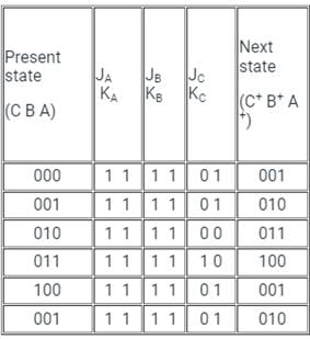
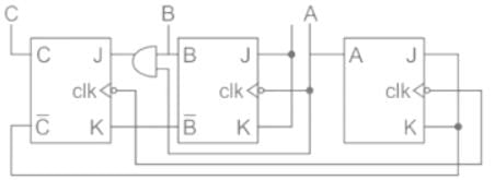
A three-bit counter arrangement is shown below. It ig given that the counter was initially 000 (C B A) Determine its count sequence for next pulses and also determine whether the counter is self-starting.
Detailed Solution for Test: Sequential Circuits - 2 - Question 15

Concept:

Asynchronous Counter:

In the asynchronous counter, we don’t use a universal clock, only first flip-flop is driven by the main clock and the clock input of the rest of the following flip flop is driven by the output of previous flip-flops.

 it is also called the RIPPLE counter.

We can understand it by the following diagram:

Synchronous Counter:

Unlike the asynchronous counter, the synchronous counter has one global clock which drives each flip flop so output changes in parallel.

The one advantage of a synchronous counter over the asynchronous counter is, that it can operate on a higher frequency than an asynchronous counter as it does not have a cumulative delay because of the same clock is given to each flip flop. 

Self-starting counter→ A counter is self-starting if it automatically goes to one of the desired states with subsequent clock pulse in case it lands itself accidentally into any of the undesired states

Analysis:

From the circuit diagram, it is clear that flip flop A and B are acting as a ripple counter as the output of A is fed as a clock signal to flip flop B

Due to the negative edge triggering the output of B toggles only when A has a transition from 1 to 0.

Given;

Initial state (C B A) → 000

Excitation for A flip flop;

JA = KA =C̅ 

Excitation for B flip flop;

JB = KB= 1

Excitation for C flip flop;

JC = A.B, KC = B̅ 

Hence, the sequence → 000, 001, 010, 011, 100.

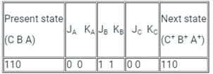
To check whether the counter is self-starting or not let's start the analysis from an unused state;

let the unused state be → 110

Since the output has stuck in 110 → Not a self-starting counter

137 videos|143 docs|71 tests
Information about Test: Sequential Circuits - 2 Page
In this test you can find the Exam questions for Test: Sequential Circuits - 2 solved & explained in the simplest way possible. Besides giving Questions and answers for Test: Sequential Circuits - 2, EduRev gives you an ample number of Online tests for practice

Top Courses for Electrical Engineering (EE)

137 videos|143 docs|71 tests
Download as PDF

Top Courses for Electrical Engineering (EE)