GATE Exam > GATE Questions > A step-up chopper shown in figure is to deliv...
Start Learning for Free
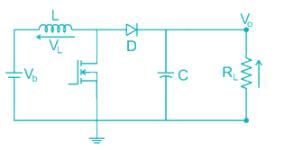
A step-up chopper shown in figure is to deliver 3A

In to the 10 Ω load. The battery voltage is 12 V, L = 20 μH, C = 100 μF and chopper frequency is 50 kHz. Determine the on-time of the chopper ________ μs

In to the 10 Ω load. The battery voltage is 12 V, L = 20 μH, C = 100 μF and chopper frequency is 50 kHz. Determine the on-time of the chopper ________ μs
Correct answer is '12'. Can you explain this answer?
Verified Answer
A step-up chopper shown in figure is to deliver 3AIn to the 10 Ω...
Calculation:
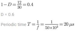
Vo = IoRL = 3 × 10 = 30 V
Vb = Vo (1 – D)

On time = TON = DT = 0.6 × 20 × 10-6 = 12 μs

Vo = IoRL = 3 × 10 = 30 V
Vb = Vo (1 – D)

On time = TON = DT = 0.6 × 20 × 10-6 = 12 μs

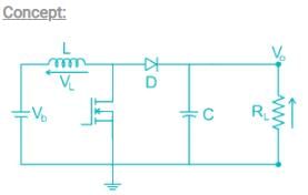
When the transistor is switched on, current ramps up in the inductor and energy is stored.
When the transistor is switched off, the inductor voltage reverses and acts together with the battery voltage to forward bias the diode, transferring energy to the capacitor.
When the transistor is switched on again, the load current is maintained by the capacitor, energy is stored in the inductor and the cycle can start again.
The value of the load voltage is increased by increasing the duty cycle or the on-time of the transistor.
During the transistor on-period, assuming an ideal inductor and transistor
Vb = VL = Ldi/dt
Vb/s = (sL) i(s)
i(s) = Vb/s2L
i(t) = (Vb/L)t = kt
Vb = VL = Ldi/dt
Vb/s = (sL) i(s)
i(s) = Vb/s2L
i(t) = (Vb/L)t = kt
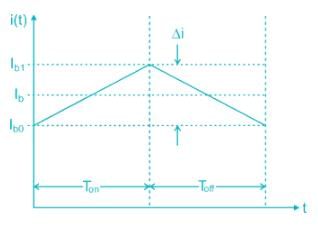
Over an on-time of TON, the change of battery current will be
Δi = k TON
Δi = k TON
During the off-period
Vo = Vb + VL = Vb + L(di/dt) = Vb + L(Δi/Δt)
= Vb + L(Vb/L)TON /Toff = Vb(1 + TON /Toff)
Vo = Vb + VL = Vb + L(di/dt) = Vb + L(Δi/Δt)
= Vb + L(Vb/L)TON /Toff = Vb(1 + TON /Toff)
Let the duty cycle
D = TON T, and Toff = T – TON = T(1 - D). Now
Vo = Vb (1 – DT/T(1 – D))
D = TON T, and Toff = T – TON = T(1 - D). Now
Vo = Vb (1 – DT/T(1 – D))
which simplifies to
Vo = Vb/(1 - D)
Vo = Vb/(1 - D)
In an ideal circuit, VbIb = V0I0. Therefore, from eq.
Ib = (Vo/Vb)Ib = Io/(1 – D)
Ib = Ib + Δi/2
Ibo = Ib – Δi/2
Ib = (Vo/Vb)Ib = Io/(1 – D)
Ib = Ib + Δi/2
Ibo = Ib – Δi/2
When the steady variation of battery current has been reached, the variation will be between lo and I1, as shown in.


|
Explore Courses for GATE exam
|

|
A step-up chopper shown in figure is to deliver 3AIn to the 10 Ω load. The battery voltage is 12 V, L = 20 μH, C = 100 μF and chopper frequency is 50 kHz. Determine the on-time of the chopper ________ μsCorrect answer is '12'. Can you explain this answer?
Question Description
A step-up chopper shown in figure is to deliver 3AIn to the 10 Ω load. The battery voltage is 12 V, L = 20 μH, C = 100 μF and chopper frequency is 50 kHz. Determine the on-time of the chopper ________ μsCorrect answer is '12'. Can you explain this answer? for GATE 2025 is part of GATE preparation. The Question and answers have been prepared according to the GATE exam syllabus. Information about A step-up chopper shown in figure is to deliver 3AIn to the 10 Ω load. The battery voltage is 12 V, L = 20 μH, C = 100 μF and chopper frequency is 50 kHz. Determine the on-time of the chopper ________ μsCorrect answer is '12'. Can you explain this answer? covers all topics & solutions for GATE 2025 Exam. Find important definitions, questions, meanings, examples, exercises and tests below for A step-up chopper shown in figure is to deliver 3AIn to the 10 Ω load. The battery voltage is 12 V, L = 20 μH, C = 100 μF and chopper frequency is 50 kHz. Determine the on-time of the chopper ________ μsCorrect answer is '12'. Can you explain this answer?.
A step-up chopper shown in figure is to deliver 3AIn to the 10 Ω load. The battery voltage is 12 V, L = 20 μH, C = 100 μF and chopper frequency is 50 kHz. Determine the on-time of the chopper ________ μsCorrect answer is '12'. Can you explain this answer? for GATE 2025 is part of GATE preparation. The Question and answers have been prepared according to the GATE exam syllabus. Information about A step-up chopper shown in figure is to deliver 3AIn to the 10 Ω load. The battery voltage is 12 V, L = 20 μH, C = 100 μF and chopper frequency is 50 kHz. Determine the on-time of the chopper ________ μsCorrect answer is '12'. Can you explain this answer? covers all topics & solutions for GATE 2025 Exam. Find important definitions, questions, meanings, examples, exercises and tests below for A step-up chopper shown in figure is to deliver 3AIn to the 10 Ω load. The battery voltage is 12 V, L = 20 μH, C = 100 μF and chopper frequency is 50 kHz. Determine the on-time of the chopper ________ μsCorrect answer is '12'. Can you explain this answer?.
Solutions for A step-up chopper shown in figure is to deliver 3AIn to the 10 Ω load. The battery voltage is 12 V, L = 20 μH, C = 100 μF and chopper frequency is 50 kHz. Determine the on-time of the chopper ________ μsCorrect answer is '12'. Can you explain this answer? in English & in Hindi are available as part of our courses for GATE.
Download more important topics, notes, lectures and mock test series for GATE Exam by signing up for free.
Here you can find the meaning of A step-up chopper shown in figure is to deliver 3AIn to the 10 Ω load. The battery voltage is 12 V, L = 20 μH, C = 100 μF and chopper frequency is 50 kHz. Determine the on-time of the chopper ________ μsCorrect answer is '12'. Can you explain this answer? defined & explained in the simplest way possible. Besides giving the explanation of
A step-up chopper shown in figure is to deliver 3AIn to the 10 Ω load. The battery voltage is 12 V, L = 20 μH, C = 100 μF and chopper frequency is 50 kHz. Determine the on-time of the chopper ________ μsCorrect answer is '12'. Can you explain this answer?, a detailed solution for A step-up chopper shown in figure is to deliver 3AIn to the 10 Ω load. The battery voltage is 12 V, L = 20 μH, C = 100 μF and chopper frequency is 50 kHz. Determine the on-time of the chopper ________ μsCorrect answer is '12'. Can you explain this answer? has been provided alongside types of A step-up chopper shown in figure is to deliver 3AIn to the 10 Ω load. The battery voltage is 12 V, L = 20 μH, C = 100 μF and chopper frequency is 50 kHz. Determine the on-time of the chopper ________ μsCorrect answer is '12'. Can you explain this answer? theory, EduRev gives you an
ample number of questions to practice A step-up chopper shown in figure is to deliver 3AIn to the 10 Ω load. The battery voltage is 12 V, L = 20 μH, C = 100 μF and chopper frequency is 50 kHz. Determine the on-time of the chopper ________ μsCorrect answer is '12'. Can you explain this answer? tests, examples and also practice GATE tests.

|
Explore Courses for GATE exam
|

|
Signup to solve all Doubts
Signup to see your scores go up within 7 days! Learn & Practice with 1000+ FREE Notes, Videos & Tests.


