Class 12 Exam > Class 12 Questions > please explain the full wave rectifier elabor...
Start Learning for Free
please explain the full wave rectifier elaborately
? Related: Junction Diode as a Rectifier
Most Upvoted Answer
please explain the full wave rectifier elaborately Related: Junction ...

Community Answer
please explain the full wave rectifier elaborately Related: Junction ...
Full Wave Rectifier using Junction Diode
- Introduction:
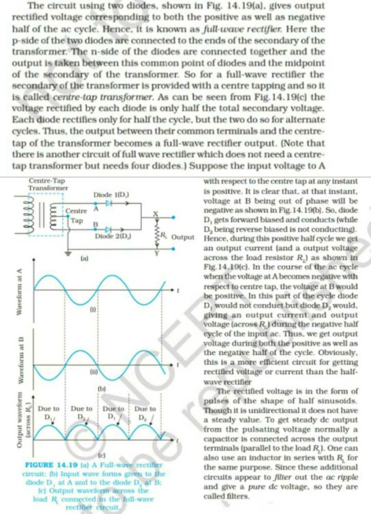
A full wave rectifier is a circuit that converts an alternating current (AC) input signal into a direct current (DC) output signal. This is achieved by using a combination of diodes to allow both halves of the AC input signal to be used.
- Working Principle:
The full wave rectifier circuit consists of two diodes connected in a "bridge" configuration. During the positive half cycle of the AC input signal, one diode conducts and allows current to flow through the load resistor in one direction. During the negative half cycle, the other diode conducts and allows current to flow through the load resistor in the opposite direction. This results in a DC output signal that is the sum of both halves of the AC input signal.
- Advantages:
1. Produces a smoother output compared to half wave rectifiers.
2. Utilizes both halves of the input signal, increasing efficiency.
3. Provides a higher average output voltage compared to half wave rectifiers.
- Disadvantages:
1. Requires four diodes instead of two.
2. More complex circuit compared to half wave rectifiers.
- Applications:
Full wave rectifiers are commonly used in power supplies, battery chargers, and other electronic devices that require a stable DC power source.
In conclusion, a full wave rectifier using junction diodes is an essential circuit for converting AC input signals into DC output signals efficiently. Its advantages include smoother output, higher efficiency, and higher average output voltage, making it a popular choice in various electronic applications.

|
Explore Courses for Class 12 exam
|

|
Similar Class 12 Doubts
please explain the full wave rectifier elaborately Related: Junction Diode as a Rectifier?
Question Description
please explain the full wave rectifier elaborately Related: Junction Diode as a Rectifier? for Class 12 2025 is part of Class 12 preparation. The Question and answers have been prepared according to the Class 12 exam syllabus. Information about please explain the full wave rectifier elaborately Related: Junction Diode as a Rectifier? covers all topics & solutions for Class 12 2025 Exam. Find important definitions, questions, meanings, examples, exercises and tests below for please explain the full wave rectifier elaborately Related: Junction Diode as a Rectifier?.
please explain the full wave rectifier elaborately Related: Junction Diode as a Rectifier? for Class 12 2025 is part of Class 12 preparation. The Question and answers have been prepared according to the Class 12 exam syllabus. Information about please explain the full wave rectifier elaborately Related: Junction Diode as a Rectifier? covers all topics & solutions for Class 12 2025 Exam. Find important definitions, questions, meanings, examples, exercises and tests below for please explain the full wave rectifier elaborately Related: Junction Diode as a Rectifier?.
Solutions for please explain the full wave rectifier elaborately Related: Junction Diode as a Rectifier? in English & in Hindi are available as part of our courses for Class 12.
Download more important topics, notes, lectures and mock test series for Class 12 Exam by signing up for free.
Here you can find the meaning of please explain the full wave rectifier elaborately Related: Junction Diode as a Rectifier? defined & explained in the simplest way possible. Besides giving the explanation of
please explain the full wave rectifier elaborately Related: Junction Diode as a Rectifier?, a detailed solution for please explain the full wave rectifier elaborately Related: Junction Diode as a Rectifier? has been provided alongside types of please explain the full wave rectifier elaborately Related: Junction Diode as a Rectifier? theory, EduRev gives you an
ample number of questions to practice please explain the full wave rectifier elaborately Related: Junction Diode as a Rectifier? tests, examples and also practice Class 12 tests.

|
Explore Courses for Class 12 exam
|

|
Signup for Free!
Signup to see your scores go up within 7 days! Learn & Practice with 1000+ FREE Notes, Videos & Tests.


