


Electrical Engineering (EE) Exam > Electrical Engineering (EE) Questions > Which logic gate is equivalent to these combi... Start Learning for Free
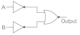
Which logic gate is equivalent to these combinations of logic gates
- a)NOR
- b)NAND
- c)AND
- d)OR
Correct answer is option 'C'. Can you explain this answer?

Verified Answer
Which logic gate is equivalent to these combinations of logic gatesa)N...
CONCEPT:
Logic gates are small electronic circuits that are used to control the output current according to our requirements.
These are the following symbols to represent logic gates
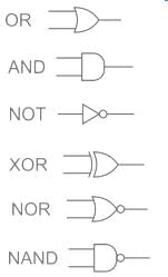
These are the Properties of logic gates:
And gate(.) – It gives us an output one only when both the inputs as 1 otherwise 0
OR gate(+) – The OR gate gives an output of 1 if either of the two inputs is 1, it gives 0 otherwise.
NOT gate(‘) – The NOT gate gives an output of 1 input is 0 and vice-versa.
NOR gate – The combination of NOT and OR gates, so it will have its output reversed.
NAND gate – The combination of NOT and AND gates, so it will have its output reversed.
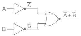
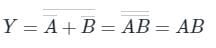
In our logic circuit, we used NOT and NOR in such a way that current from both A and B will pass through NOT gates and then send to the NOR gate hence the Truth table of the following circuit will be:
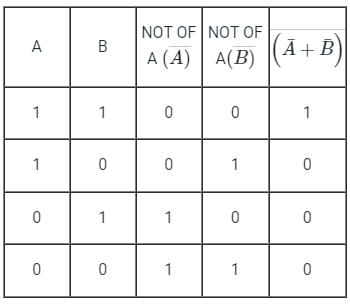
This means the output will be always 1 when both inputs are 1, just like the AND gate.
Logic gates are small electronic circuits that are used to control the output current according to our requirements.
These are the following symbols to represent logic gates
These are the Properties of logic gates:
And gate(.) – It gives us an output one only when both the inputs as 1 otherwise 0
OR gate(+) – The OR gate gives an output of 1 if either of the two inputs is 1, it gives 0 otherwise.
NOT gate(‘) – The NOT gate gives an output of 1 input is 0 and vice-versa.
NOR gate – The combination of NOT and OR gates, so it will have its output reversed.
NAND gate – The combination of NOT and AND gates, so it will have its output reversed.
In our logic circuit, we used NOT and NOR in such a way that current from both A and B will pass through NOT gates and then send to the NOR gate hence the Truth table of the following circuit will be:
This means the output will be always 1 when both inputs are 1, just like the AND gate.
Most Upvoted Answer
Which logic gate is equivalent to these combinations of logic gatesa)N...
CONCEPT:
Logic gates are small electronic circuits that are used to control the output current according to our requirements.
These are the following symbols to represent logic gates
These are the Properties of logic gates:
And gate(.) – It gives us an output one only when both the inputs as 1 otherwise 0
OR gate(+) – The OR gate gives an output of 1 if either of the two inputs is 1, it gives 0 otherwise.
NOT gate(‘) – The NOT gate gives an output of 1 input is 0 and vice-versa.
NOR gate – The combination of NOT and OR gates, so it will have its output reversed.
NAND gate – The combination of NOT and AND gates, so it will have its output reversed.
In our logic circuit, we used NOT and NOR in such a way that current from both A and B will pass through NOT gates and then send to the NOR gate hence the Truth table of the following circuit will be:
This means the output will be always 1 when both inputs are 1, just like the AND gate.
 | Explore Courses for Electrical Engineering (EE) exam |
Top Courses for Electrical Engineering (EE)View all


Top Courses for Electrical Engineering (EE)
Question Description
Which logic gate is equivalent to these combinations of logic gatesa)NORb)NANDc)ANDd)ORCorrect answer is option 'C'. Can you explain this answer? for Electrical Engineering (EE) 2026 is part of Electrical Engineering (EE) preparation. The Question and answers have been prepared according to the Electrical Engineering (EE) exam syllabus. Information about Which logic gate is equivalent to these combinations of logic gatesa)NORb)NANDc)ANDd)ORCorrect answer is option 'C'. Can you explain this answer? covers all topics & solutions for Electrical Engineering (EE) 2026 Exam. Find important definitions, questions, meanings, examples, exercises and tests below for Which logic gate is equivalent to these combinations of logic gatesa)NORb)NANDc)ANDd)ORCorrect answer is option 'C'. Can you explain this answer?.
Which logic gate is equivalent to these combinations of logic gatesa)NORb)NANDc)ANDd)ORCorrect answer is option 'C'. Can you explain this answer? for Electrical Engineering (EE) 2026 is part of Electrical Engineering (EE) preparation. The Question and answers have been prepared according to the Electrical Engineering (EE) exam syllabus. Information about Which logic gate is equivalent to these combinations of logic gatesa)NORb)NANDc)ANDd)ORCorrect answer is option 'C'. Can you explain this answer? covers all topics & solutions for Electrical Engineering (EE) 2026 Exam. Find important definitions, questions, meanings, examples, exercises and tests below for Which logic gate is equivalent to these combinations of logic gatesa)NORb)NANDc)ANDd)ORCorrect answer is option 'C'. Can you explain this answer?.
Solutions for Which logic gate is equivalent to these combinations of logic gatesa)NORb)NANDc)ANDd)ORCorrect answer is option 'C'. Can you explain this answer? in English & in Hindi are available as part of our courses for Electrical Engineering (EE). Download more important topics, notes, lectures and mock test series for Electrical Engineering (EE) Exam by signing up for free.
Here you can find the meaning of Which logic gate is equivalent to these combinations of logic gatesa)NORb)NANDc)ANDd)ORCorrect answer is option 'C'. Can you explain this answer? defined & explained in the simplest way possible. Besides giving the explanation of Which logic gate is equivalent to these combinations of logic gatesa)NORb)NANDc)ANDd)ORCorrect answer is option 'C'. Can you explain this answer?, a detailed solution for Which logic gate is equivalent to these combinations of logic gatesa)NORb)NANDc)ANDd)ORCorrect answer is option 'C'. Can you explain this answer? has been provided alongside types of Which logic gate is equivalent to these combinations of logic gatesa)NORb)NANDc)ANDd)ORCorrect answer is option 'C'. Can you explain this answer? theory, EduRev gives you an ample number of questions to practice Which logic gate is equivalent to these combinations of logic gatesa)NORb)NANDc)ANDd)ORCorrect answer is option 'C'. Can you explain this answer? tests, examples and also practice Electrical Engineering (EE) tests.
| Explore Courses for Electrical Engineering (EE) exam |
Top Courses for Electrical Engineering (EE)
Explore Courses
Signup for Free!
Signup to see your scores go up within 7 days! Learn & Practice with 1000+ FREE Notes, Videos & Tests.


