BJT & FET - 2 | Electrical Engineering SSC JE (Technical) - Electrical Engineering (EE) PDF Download
| Table of contents |

|
| The Field Effect Transistor (FET) |

|
| Schematic Symbols |

|
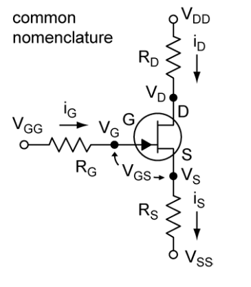
| Common Nomenclature (n-channel FET example) |

|
| Common Specifications |

|
| Common Circuit Applications |

|
The Field Effect Transistor (FET)
- FETs is a three-terminal device like the BJT but operates by a different principle.
- The three terminals are called the source, drain, and gate.
- The voltage applied to the gate controls the current flowing in the source-drain channel. No current flows through the gate electrode, thus the gate is essentially insulated from the source-drain channel.
- Because no current flows through the gate, the input impedance of the FET is extremely large (in the range of 1010–1015 Ω). The large input impedance of the FET makes them an excellent choice for amplifier inputs.
- The two common families of FETs, the junction FET (JFET) and the metal oxide semiconductor FET (MOSFET) differ in the way the gate contact is made on the source-drain channel.
- In the JFET the gate-channel contact is a reverse biased pn junction. The gate-channel junction of the JFET must always be reverse biased otherwise it may behave as a diode.
- All JFETs are depletion mode devices—they are on when the gate bias is zero (VGS = 0).
- In the MOSFET the gate-channel contact is a metal electrode separated from the channel by a thin layer of insulating oxide. MOSFETs have very good isolation between the gate and the channel, but the thin oxide is easily damaged (punctured!) by static discharge through careless handling.
- MOSFETs are made in both depletion mode (on with zero biased gate, VGS = 0) and in enhancement mode (off with zero biased gate).
In this Document we will focus on JFETs.
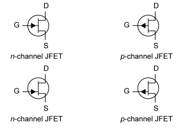
Schematic Symbols
- Two versions of the symbols are in common use. The symbols in the top row depict the source and drain as being symmetric. This is not generally true.
- Slight asymmetries are built into the channel during manufacturing which optimize the performance of the FET. Thus, it is necessary to distinguish the source from the drain.
- In this EduRev document, we will use the asymmetric symbols found on the bottom row, which depict the gate nearly opposite the source. The designation n-channel means that the channel is n doped and the gate is p doped. The p-channel is complement of n-channel.
Common Nomenclature (n-channel FET example)
Regions of JFET Operation
- Cut-off region: The transistor is off. There is no conduction between the drain and the source when the gate-source voltage is greater than the cut-off voltage. (ID = 0 for VGS > VGS,off)
- Active region (also called the Saturation region): The transistor is on. The drain current is controlled by the gate-source voltage (VGS) and relatively insensitive to VDS. In this region the transistor can be an amplifier.

- Ohmic region: The transistor is on, but behaves as a voltage controlled resistor. When VDS is less than in the active region, the drain current is roughly proportional to the source-drain voltage and is controlled by the gate voltage.

Common Specifications
IDSS is the drain current in the active region for VGS = 0. (ID source shorted to gate)
VGS,off is the minimum VGS where ID = 0. VGS,off is negative for n-channel and positive
for p-channel.
gm is the transconductance, the change in ID with VGS and constant VDS.

Common Circuit Applications
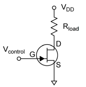
Voltage Controlled Switch. For the on state the gate voltage VGS = 0 and for the off
state |VGS| > |VGS,off| (of great magnitude than VGS,off and with the same sign). The sign of
the voltage depends on the type of FET, negative for n-channel and positive for p-channel.
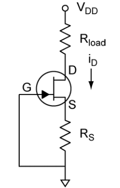
Current Source: The drain current is set by RS such that VGS = IDRS. Any value of
current can be chosen between zero and IDSS (see the ID vs VGS graph for the JFET).
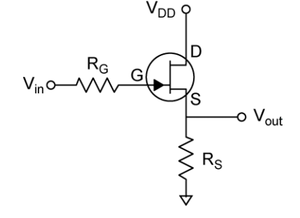
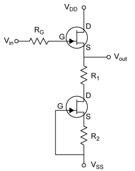
Source Follower: The simple source follower is shown below. The improved version is shown at the right. The lower JFET forms a current source. The result is that VGS is held constant, removing the defects of the simple circuit.
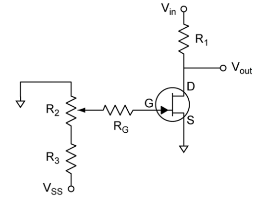
Voltage-Controlled Resistor: VGS must be between zero and VGS,off.
JFET Diode: The JET pn gate junction can be used as a diode by connecting the source and the drain terminals. This is done if very low reverse leakage currents are required. The leakage current is very low because the reverse leakage current scales with the gate area. Small gate areas are designed into JFETs because it decreases the gate-source and the gate-drain capacitances.

|
23 videos|98 docs|42 tests
|
FAQs on BJT & FET - 2 - Electrical Engineering SSC JE (Technical) - Electrical Engineering (EE)
| 1. What is the schematic symbol for a field effect transistor (FET)? |  |
| 2. What is the common nomenclature used for an n-channel FET? |  |
| 3. What are some common specifications of FETs? |  |
| 4. What are some common circuit applications of FETs? |  |
| 5. What are some frequently asked questions about the differences between BJT and FET? |  |


