Carry Logic & Rotate Select | Digital Electronics - Electrical Engineering (EE) PDF Download

Carry Logic and Rotate Select
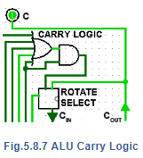
The carry logic circuit shown in Fig. 5.8.7 prevents the carry flag being set in rotate right mode, as bits rotate from bit 0 and re-enter the shift register at bit 7, therefore allowing correct carry flag operation in both left and right rotate modes.
When the ROTATE input is at logic 1, the Rotate Select circuit in Fig 5.8.7 allows COUT from the shift register to be fed back to the shift register CIN input for continuous bit rotation.
ALU Operation
Addition
To perform an addition, input data B is added to A. This is achieved by putting logic 1 on the control inputs of multiplexers 1, 2 and 3. This causes data A and B to be applied to the adder inputs. Also, to allow any carry bit from the CIN input to be included in the addition, the 1 bit carry multiplexer must have logic 0 on its control input. The shift register is only used as a PIPO register in addition mode, so its input lines R/~L and ROTATE must be at logic 0. SHIFT/~LE must also be at logic 0 to enable parallel loading of the shift register, which will hold the result of the addition (A plus B) after the application of a single CK pulse.
|
125 videos|83 docs|58 tests
|
FAQs on Carry Logic & Rotate Select - Digital Electronics - Electrical Engineering (EE)
| 1. What is carry logic and rotate select? |  |
| 2. How does carry logic work in digital systems? | |
| 3. What is the purpose of rotate select in digital systems? | |
| 4. Can carry logic and rotate select be used together in digital systems? | |
| 5. Are carry logic and rotate select important in computer architecture? | |


MCQs
,Previous Year Questions with Solutions
,Summary
,Semester Notes
,practice quizzes
,Exam
,Important questions
,ppt
,Extra Questions
,video lectures
,Objective type Questions
,Carry Logic & Rotate Select | Digital Electronics - Electrical Engineering (EE)
,study material
,Free
,Carry Logic & Rotate Select | Digital Electronics - Electrical Engineering (EE)
,shortcuts and tricks
,Sample Paper
,past year papers
,Viva Questions
,mock tests for examination
,Carry Logic & Rotate Select | Digital Electronics - Electrical Engineering (EE)
;


Carry Logic & Rotate Select Free PDF Download
Importance of Carry Logic & Rotate Select
Carry Logic & Rotate Select Notes
Carry Logic & Rotate Select Electrical Engineering (EE) Questions
Study Carry Logic & Rotate Select on the App
|
© EduRev
|
Education Revolution
|


|


within 7 days!