Mechanical Properties of Metals | Mechanical Engineering SSC JE (Technical) PDF Download
Mechanical Properties of Metal
Mechanical properties of metal indicate the nature of its inherent behavior under the action of the external force.
Or, we can say mechanical properties are the properties of the metal which are associated with its ability to resist failure under the action of external forces.
Some of the most important Mechanical properties of the metal are:
1. Ductility
- Ductility is the property by virtue of which material can be stretched to a reduced section under the action of tensile force.
- Large deformations are thus possible in ductile materials before the absolute failure or rupture takes place, some of the examples are mild steel, aluminium, copper, manganese, lead, nickel, brass, bronze, monal metal etc.

2. Brittleness
- Brittleness is the lack of ductility i.e. material can not be stretched. In brittle materials, failure takes place with a relatively smaller deformation. This property is undesirable. For brittle materials fracture point & ultimate points are same, and after proportional limit very small strain is seen. Some of the examples are cast iron, concrete and glass.
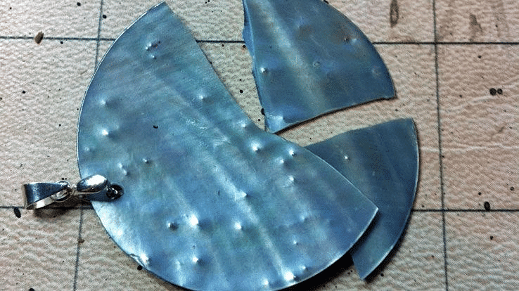
 Brittle Metal
- To distinguish between these two types of materials, materials with strain less than 5% at fracture point are regarded as brittle and those having strains greater than 5% at fracture point are called ductile. (This value for mild steel at fracture is about 25%).
3. Malleability
- The property by which a material can be uniformly extended in all direction without rupture. A malleable material possess a high degree of plasticity. This property is of great use in operations like forging, hot rolling, drop (stamping) etc.

4. Toughness
- The property which enables materials to absorb energy without fracture. This property is very desirable in case of cyclic loading or shock loading.
- The “Modulus of toughness” is measured as area under entire stress-strain curve and is the energy absorbed by material of the specimen per unit volume upto fracture stage.
Modulus of toughness

where,
Sty is the tensile yield strength,
Stu is the tensile ultimate strength,
εy is the strain at yield,
εu is the ultimate strain (total strain at failure), and
E is the elastic modulus.- The modules of toughness will depend upon ultimate tensile strength and strain at failure (fracture strain). Hence the material which is very ductile will exhibit a higher modulus of toughness as the case with mild steel.
- On the other hand the “Modulus of resilience” depends upon yield strength and hence a material with higher yield strength will have higher modulus of resilience
- The ‘Modulus of resilience’ is the maximum elastic energy per unit volume that can be absorbed without attaining plastic stage.
Modulus of resilience (u)=
- Higher toughness a desirable property in materials used for gears, chains, crane hooks, freight car etc. Higher resilience is desirable in springs.
5. Hardness
- Hardness is defined as the resistance to indentation or scratching or surface abrasion.
- Based upon this there are two methods of hardness measurement :
(i) Scratch hardness - Commonly measured by Mohr's test.
(ii) Indentation hardness (abrasion) measured by deformation.
1. Brinell hardness method
2. Rockwell hardness
3. Vickers hardness
4. Knoop hardness - It should be noted that ductile materials are tough and brittle materials are hard.
6. Fatigue
- It has been found that material behave differently under the static loading and dynamic loading.
- The behaviour of material under variable loads (dynamic loads) is referred to as “fatigue”. In recent past several failures of structures have been noted due to fatigue.
- Factors affecting fatigue are:
(i) Loading conditions
(ii) Frequency of loading
(iii) Corrosion
(iv) Temperature
(v) Stress concentration
7. Creep & Stress Relaxation
- At any temperature, a material will progressively deform with the passage of time under constant loading, even if the stress is below yield point, this phenomenon is called creep. However such deformation is negligibly small at lower temperature.
- At higher temperature, due to greater mobility of atoms, most of the material sloose their strength and elastic constants also get reduced. Hence greater deformation at elevated temperature results even under constant loading. Therefore creep is more pronounced at higher temperature, hence it must be considered for design of engines & furnaces.
- The temperature at which the creep becomes very appreciable is half of the melting point temperature on absolute scale and is known as “Homologous temperature”.
- If a wire of metal is stretched between two immovable supports, so that it has an initial tension stress so. The stress in the wire gradually diminishes, eventually reaching a constant value. This process, which is a manifestation of creep, is called “Stress relaxation”.
|
5 videos|103 docs|59 tests
|
FAQs on Mechanical Properties of Metals - Mechanical Engineering SSC JE (Technical)
| 1. What are the common mechanical properties of metals? |  |
| 2. How are the mechanical properties of metals tested? |  |
| 3. What is the difference between strength and hardness in metals? |  |
| 4. How does ductility affect the performance of metals in engineering applications? |  |
| 5. Why is it important to understand the mechanical properties of metals in material selection for manufacturing processes? |  |
|
5 videos|103 docs|59 tests
|

|
Explore Courses for Mechanical Engineering exam
|

|


