Beams - 1 | Civil Engineering SSC JE (Technical) - Civil Engineering (CE) PDF Download
CONCRETE DESIGN
BEAMS AND SLABS
(I) Working Stress Method
A. Some important terms
(a) Modular Ratio (m): It is the ratio of modulus of elasticity of steel to that of concrete
Where, Es = Young's modulus of elasticity of steel = 2 × 10⁵ N/mm2(for all types of steel),σcbc= Permissible stress in concrete in bending compression ,Ec = Modulus of elasticity of concrete
(b) Equivalent Areas of Composite Section
Consider an R.C.C. section shown in Fig below subjected to a compressive load P.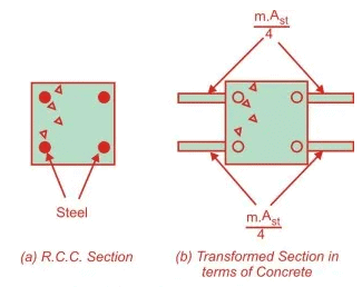
Let
A = Area of cross-section
Ac = Area of concrete
Ast = Area of steel
m = Modular ratio
Ss = Stress in steel
Sc = Stress in concrete
es = Strain in steel
ec = Strain in concrete
Ps = Load carried by steel
Pc = Load carried by concrete
Aeqc = Equivalent area of section in terms of concrete
Es = Yong’s modulus of elasticity of steel
Ec = Young’s modulus of elasticity of concrete
P=Ps+Pc
The bond between steel and concrete is assumed to be perfect so the strains in steel and the surrounding concrete will be equal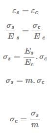
It means that stress in steel is m times the stress in concrete or load carried by steel is m times the load carried by concrete of equal area. Using Eqns. (i) and (ii)
The expression in the denominator
is called the equivalent area of the section in terms of concrete. It means that the area of steel Ast, can be replaced by an equivalent area of concrete equal to m.Ast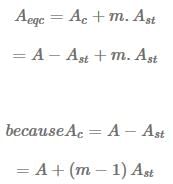
Therefore, the concept of modular ratio makes it possible to transform the composite section into an equivalent homogeneous section, made up of one material.
(c) Assumptions in working stress method:
-Plane Section before bending will remain plane after bending
-Bond between steel and concrete is perfect with in elastic limit of steel.
-The steel and concrete behaves as linear elastic material
-All tensile stresses are taken by reinforcement and none by concrete
-The stresses in steel and concrete are related by a factor known as “modular ratio
-The Stress-strain relationship of steel and concrete is a Straight line under working load
(d) Effective Length
- Simply supported beams and slabs (Ieff)

leff = minimum 
Here, l0 = clear span
w = width of support
d = depth of beam or slab
- For continuous beam
(i) If width of support < (1/12) of clear span
leff = minimum 
(ii) If width of support > (1/12) of clear span
(a) When one end fixed other end continuous or both end continuous. lef = l0

(b) When one end continuous and other end simply supported.
leff = minimum (1 + w / 2,1 + d / 2)
- Cantilever


- Frames

leff = Centre to Centre distance
In the analysis of continuous frame centre to centre distance shall be used.
(e) Control of Deflection
(i) This is one of the most important check for limit state of serviceability.
(a) The final deflection due to all loads including the effect of temperature, creep and shrinkage and measured from as cast level of the support of floors, roofs and other horizontal members should not and other horizontal members should not normally exceed span/250
(b) The deflection including the effect of temperature, creep and shirnkage occuring after erection of partition and application of finishes should not normally exceed
span/350 or 20 mm which ever is less.
(ii) The vertical deflection limit may generally be assumed to be satisfied provided that span to depth ratio are not greater than the value obtained as below: (a) Basic span to effective depth ratio for span upto 10 m is
Type of beams:span/ effective depth
For Cantilever — 7
For simply supported — 20
For continuous — 26
(b) For span > 10 m effective depth
where 'A' is span to effective depth ratio for span upto 10m.
(c) Depending upon the tension reinforcement the value 'A' can be modified by multiplying a factor called modification factor (MF1) effective depth =


(d) Depending upon area of compression reinforcement, value (A) can be further modified using a modification factor (MF2) effective depth =

(e) For flanged beam : A reduction factor is used
(f) Deflection check for two way slab:
Slenderness Limit:
1. For simply supported or continuous beams.

where, l0 = Clear span
B = Width of the section and
d = Effective depth
2. For Cantilever beam
(i) Minimum tensions reinforcement
(ii) Maximum tension reinforcement = 0.04bD
(iii) Maximum compression reinforcement = 0.04 bD
where D = overall depth of the section
(iv) Where D > 750 mm, side face reinforcement is provided and it is equal to 0.1% of gross cross-section area (b × D). It is provided equally on both face.
(v) Maximum spacing of side face reinforcement is 300 mm.
(v) Maximum size of reinforcement for slab/beam is 1/8 of total thickness of the member.
(vi) Nominal cover for different members
Beams — 30 mm
Slab — 20 to 30 mm
Column — 40 mm
Foundation — 50 mm
(vii) Moment and shear coefficiently beam/slabs

One way slab: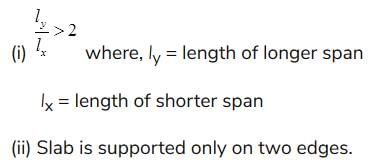
Two way slab:
(i) 
(ii) Slab is supported on all edges.
(g) Permissible value of strength in concrete in tension for mild steel 

- ζ bd given in table is only for plain mild steel bar in tension.
- ζ bd value should be increased by 60% for deformed bars both in LSM and WSM.
- For bars in compression the value should be increased by 25%.
(h) Permissible stresses in steel
(Clauses B-2.2, B-2.2.1, B -2.3 an B-4.2)


Chapter 2 Beams (Part 2)
B. Analysis (a) Singly reinforced rectangular section (i) Actual depth of neutral axis (Xa)
Here, B = Width of beam D = Overall depth d = Effective depth
s = C = permissible stress in concrete s = t = st permissible stress in steel In working stress method, actual depth neutral axis is calculated by equating moment of area on both sides of neutral sides.
On compression side, Moment of area = 2
X
B.X . a
a On tension side = ( m.A st ) (d – X a ) For actual depth of NA mA (d X ) 2
BX
a
st
2
a
-
=
(ii) Critical depth of Neutral Axis (Xc)
Critical depth of neutral axis is that depth at which stresses in concrete and steel are attained to its maximum permissible values at the same time.
From similar triangle
k is called critical neutral axis depth factor
(iii) Moment of resistance: Maximum capacity of taking moment of a given RCC sections is called moment of resistance. 1. For Balanced section (Xa = Xc):
Moment of resistance = compressive force x lever arm or total tensile force × lever arm
lever arm = distance between C and T
Moment of resistance for a balanced section,
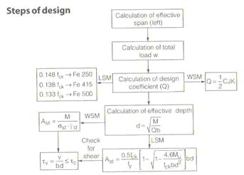
or balanced section Design of Beam For a given BM = M Equating BM = Mr M = Q.B.d2
Where, Q = moment of resistance coefficient Area of steel for a balanced section BM = Mr
(For balance section)
2. For under reinforced section (Xa < Xc)
Here,
Xa < Xc Ca < s cbc ta = sst From similar triangle
Properties Steel gets its maximum permissible value first, concrete is under stressed. Failure of section will be due to steel. Failure of section is called ductile failure It provides sufficient time before failure this type of section is preferred. 3. For over-reinforcement section (Xa > Xc)
Properties: Concrete gets its maximum permissible value first, steel is under stressed. Failure takes place due to failure of concrete Failure of concrete is sudden (brittle failure) this type of structure should be avoided. (b) Doubly reinforced section If depth and width are restricted.
If this beam has to support a BM more than Mr of the balanced section.
Ther are 2 options.
Provide an over-reinforced section, or Provide a doubly Reinforcement-section Over re-inforced section has many disadvantage like brittle failure so always a doubly reinforced section is a better option.
Properties Steel is provided on both side of NA Permissible stress for compression steel = 1.5 mC where C' = stress in concrete around compression steel. Equivalent area of steel in terms of concrete for compression steel = 1.5 mAsc For tension steel equivalent area = mAst. (i) A ct ual Dep t h of N eut r al A xi s, (X a)
Equating moment of area on both sides of NA ( )( ) ( a ) st
c sc a
2
a 1.5m – 1 A X d mA d X 2
BX
-
+ - =
Here, Xa = Actual depth of Neutral axis (ii) Critical Depth of Neutral Axis, (Xc) .d t mc m
X c
c
+
=
(iii) Moment of Resistance (Mr)
C' can be calcualted using similar triangles For a balanced section Xa= Xc Ca = s cbc
Properties
• Steel gets its maximum permissible value first, concrete is under stressed.
• Failure of section will be due to steel.
• Failure of section is called ductile failure
• It provides sufficient time before failure this type of section is preferred.
3. For over-reinforcement section (Xa > Xc)
Properties:
• Concrete gets its maximum permissible value first, steel is under stressed.
• Failure takes place due to failure of concrete
• Failure of concrete is sudden (brittle failure) this type of structure should be avoided.
|
2 videos|122 docs|55 tests
|
FAQs on Beams - 1 - Civil Engineering SSC JE (Technical) - Civil Engineering (CE)
| 1. What are beams in the context of structural engineering? |  |
| 2. What is the purpose of beams in construction? |  |
| 3. What are the different types of beams? |  |
| 4. What factors are considered in the design of beams? |  |
| 5. How are beams analyzed in structural engineering? |  |
|
2 videos|122 docs|55 tests
|

|
Explore Courses for Civil Engineering (CE) exam
|

|


