Chapter - 2 Network Theory | Additional Study Material for Mechanical Engineering PDF Download
1. Network Solution Methodology
1. Network Solution Methodology
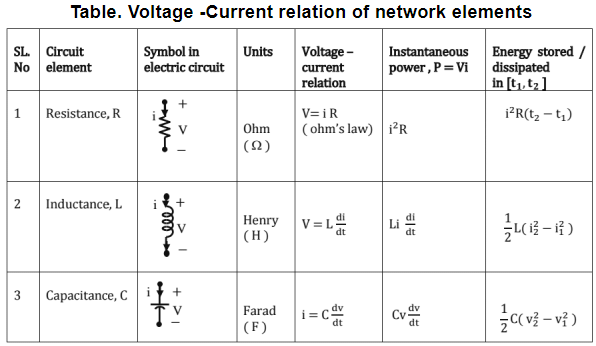
Voltage - current relation of network elements
Series and parallel connection of circuit elements R = R1 + R2 + ............... + Rn

 L = L1 + L2 + .............. + Ln
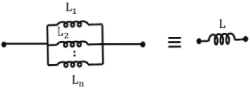


 C = C1 + C2 + .............. + Cn
Fig. Series and parallel connection of circuit elements
Kirchoff's Current Law (KCL): The algebraic sum of currents at a node in an electrical circuit is equal to zero.
Kirchoff's Voltage Law (KVL): ln any closed loop electrical circuit, the algebraic sum of voltage drops across all the circuit elements is equal to EMF rise in the same.
Mesh Analysis: In the mesh analysis, a current is assigned to each window of the network such that the currents complete a closed loop. They are also referred to as loop currents. Each element and branch therefore will have an independent current. When a branch has two of the mesh currents, the actual current is given by their algebraic sum. Once the currents are assigned, Kirchhoff s voltage law is written for each of the loops to obtain the necessary simultaneous equations. The simultaneous equations obtained can be solved using matrix inversion method or crammer's rule.
Mesh Analysis (using super mesh): When two of the loops have a common element as a current source, mesh analysis is not applied to both loops separately. Instead both the loops are merged and a super mesh is formed. Now KVL is applied to super mesh.
Nodal Analysis: Typically, electrical networks contain several nodes, where some are simple nodes and some are principal nodes, ln the node voltage method, one of the principal nodes is selected as the reference and equations based on KCl are written at the other principal nodes with respect to the reference node. At each of these other principal nodes, a voltage is assigned, where it is understood that this voltage is with respect to the reference node. These voltage are the unknowns and are determined by nodal Analysis. When the node voltages to be found by nodal analysis are more than one, the node voltages can be found from simultaneous equations by matrix inversion method or Cramer's rule.
Nodal analysis (including super node): When two of the nodes have a common element as a voltage source, nodal analysis is not applied to both the nodes separately. Instead both the nodes are merged and a super node is formed. Now KCL is applied to super node.
Voltage /Current Source
Ideal vs. Practical voltage source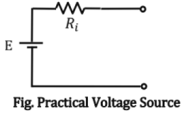
Here E is the EMF of source and Rj is the internal resistance of the source. For an ideal source, Ri is zero and for a practical source, Rx is finite and small.
Ideal vs. Practical current source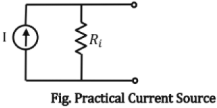
Here 1 is the current of source and Ri is internal resistance of source. For an ideal current source, Ri is infinite and for a practical source, Ri is finite and large.
Dependent Sources: A source is called dependent if voltage / current of the source depends on voltage / current in some other part of the network. Depending upon the nature of the source, dependent sources can be classified as below.
- Voltage Controlled Voltage Source (VCVS)
- Voltage Controlled Current Source (VCCS)
- Current Controlled Voltage Source (CCVS)
- Current Controlled Current Source (CCCS)
Superposition theorem: In a linear bilateral network, the current through or voltage across any element is equal to algebraic sum of currents through (or voltages across) the elements when each of the independent sources are acting alone, provided each of the independent sources are replaced by corresponding internal resistances.
Source conversion theorem: Source conversion theorem states that a voltage source, B in series with resistance, Ri as seen from terminals a and b is equivalent to a current source, I = R/Ri in parallel with resistance, Ri.
Thevenin’s and Norton's Theorems: Any linear/bilateral network as viewed from terminals A and B can be replaced by a voltage source in series with resistance. The theorem is mainly helpful to draw the load characteristics (output voltage v/s output current as load resistance is varied).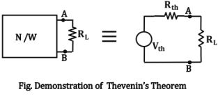
In the figure shown above, Vth is Thevenin's voltage as viewed from terminal A & B and Rth is Thevenin's resistance as viewed from terminals A & B.
Norton's Theorem: Any linear / bilateral network, as viewed from terminals A and B, can be replaced by a current source in parallel with resistance. When source conversion theorem is applied for a Thevenin's equivalent circuit, Norton equivalent circuit is obtained and vice versa.
Let ln = Norton current as between terminals A & B and
Rn = Norton Resistance as viewed from terminals A & B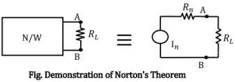
Evaluation of Thevenin's / Norton's equivalent circuit:
Let Voc = open- circuit voltage between terminals A & B,
Ish = short - circuit current between terminals A & B,
R = Resistance as viewed from terminals A & B,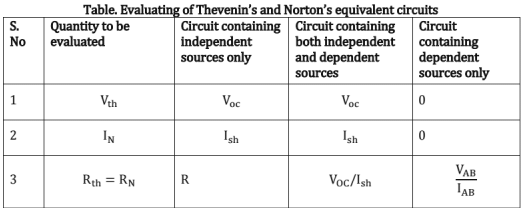
Where VAB is the voltage for a current source, IAB between the terminals A and B.
Maximum power transfer theorem (as applied to dc network): Maximum power transfer theorem in a dc network states a condition on load resistance for which the maximum power is transferred to the load resistance. In a dc network, maximum power is transferred to the load when the load resistance is equal to Thevenin's ( / Norton's) resistance as viewed from load terminals.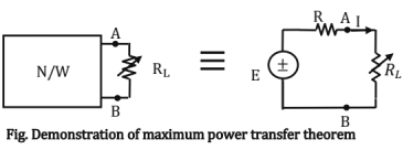
For maximum power transfer, RL = R
Total power consumed in the circuit = 
Star-Delta transformation: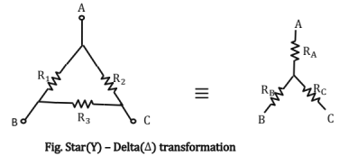

McMillan Theorem: McMillan theorem can be applied to the circuits of the form shown and is based on nodal analysis.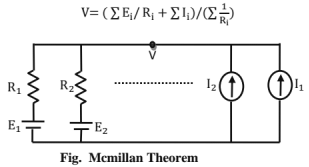
Substitution theorem: Substitution theorem can be used to get incremental change in voltage/current of any circuit element when a resistance R is changed by AR and the same can be found by inserting a voltage source - I. ΔR in series with R.
Reciprocity theorem: Reciprocity theorem states that in a linear bilateral network, voltage source and current sink can be interchanged.
Following are the conditions to be satisfied to apply reciprocity theorem
- Only one source is present
- No dependent sources are present
- No initial conditions (⇒ zero state)
Circuit which satisfies above conditions is called 'Reciprocity network".
2. Transient/Steady State Analysis of RLC Circuits to dc Input
2. Transient/Steady State Analysis of RLC Circuits to dc Input
Transient response analysis of network elements
Transient analysis of a resistive circuit
Any change in voltage across a resistor at any instant t is instantaneously felt as corresponding change in current at the same instant t. Consider the circuit below in which S is moved from position 1 to 2 at t = 0.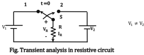

∴ Resistor allows abrupt changes in voltage and current.
Transient response of inductor
The voltage across and current through an inductor are related by following equation 
Also inductor doesn't allow abrupt change in current and for a abrupt change in current inductor requires infinite voltage to be applied across it. Also at steady state, inductor acts as short
∴ iL(t+) = iL(t-), at every instant t
Transient response of Capacitor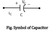
The voltage across or current through a capacitor are related by,
The voltage across a capacitor cannot change instantaneously unless infinite current (impulse) is passed through it. Hence capacitor doesn't allow abrupt change in voltage across it. Also at steady state, capacitor acts as open.
∴ vc (t-) = vc(t+) at every instant t
Transient response of a R-L circuit
Consider the R - L circuit shown below, in which switch S is moved from position 1 to 2 at t = 0.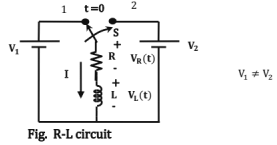

As VL(0+) ≠ VL(0-), inductor allows abrupt change in voltage. Also, l(0+) = I(0-) as inductor does not allow abrupt change in current. Consider a R - L circuit which contains only one inductor and more than one resistor as shown.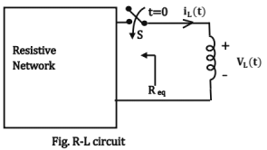
To find iL(t) for t ≥ 0 in the circuit shown above,
- Find initial value of current through inductor, li = iL(0-)
- Find steady state value of current through inductor, If = iL(∞)
- Find Req as seen from terminals of inductor
- Use following equation to find iL(t)

Transient response of a R-C circuit: Consider the R -C circuit shown below, in which switch S is moved from position 1 to position 2 at t = 0.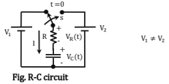

As I(0+) ≠ I(0-), capacitor allows abrupt change in current. Also, Vc (0+) = Vc (0-) as capacitor doesn't allows abrupt change in voltage. Consider a R- C circuit which contains only one capacitor and more than one resistor as shown.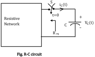
To find Vc (t) for t ≥ 0
- Find initial value of voltage across capacitor, Vi = Vc (0-)
- Find steady state value of voltage across capacitor, Vf = Vc (∞)
- Find Req as seen from terminals of capacitor
- Use following equation to find Vc(t)

Transient response analysis of a source free series R-L-C circuit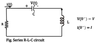

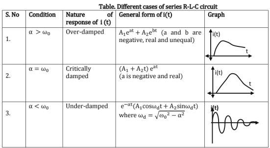
Here A1, A2 can be found using initial conditions.
Transient response analysis of a source free parallel R L C circuit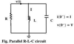

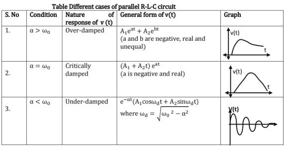
Generalization of response f (t) for an excitation g (t)
In any general R-L-C circuit, let f(t) be the response for an excitation g(t). The response f(t) can be generalized as below.
∴ f(t) = ff(t) + fn(t)
Here, fn(t) is called natural response and is found based on initial conditions assuming no source is present and ff(t) is called forced response which is derived based on source of excitation.
3. Sinusoidal Steady State Analysis
3. Sinusoidal Steady State Analysis
Phasor representation
Any sinusoidal representation, V(t) = Vm sin(ωt + ∅) can be represented in phasor form as, 
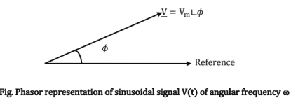
For phasor analysis of V1(t) and V2(t), following conditions should be satisfied,
- V1(t) and V2(t) should have same sign for Vm1 and Vm2.
- Both V1(t) and V2(t) should be written as sine/cosine waves.
- both V1(t) and V2(t) should have same frequency.
Impedance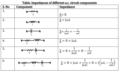
Sinusoidal excitation of different components
Excitation to resistor
Excitation to Inductor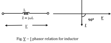
Sinusoidal excitation to Capacitor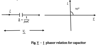
Sinusoidal excitation to RL circuit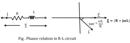
Excitation to R-C Circuit
Root mean square (rms) value of a periodic signal
The rms value of a periodic signal is defined as equivalent dc signal which will consume same power as periodic signal. If V (t) is a periodic signal of period T,
Consider a signal, V'(t) = 

Average value of a periodic signal
Average value of a periodic signal gives an idea about d.c. content of the signal. If V(t) is signal of period T,
Average power supplied by a.c. source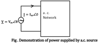
Apparent power, 
Active power, 
Reactive power, 
Active power is the power supplied to resistive part of the network and is measured in watt. Reactive power is the power supplied to inductive or capacitive part of the network and is measured in var. Power factor (PF) of circuit as seen from source is given as cos (θ - ∅). Pf gives an idea about part of VA supplied to resistive part of network.
Resonance
At resonance, voltage and current as seen from supply are in phase. Also at resonance, impedance as seen from supply is completely resistive.
Single phase Circuit analysis
Most of the analysis techniques used for dc networks can be used for ac networks also. However, algebraic operations should be replaced by phasor operations and all the theorems can be relevantly applied.
Maximum Power transfer theorem
Maximum power transfer theorem gives an idea about the maximum power consumed in ZL depending on the nature of ZL. Consider an a.c. network and corresponding Thevenin's equivalent as seen from load terminals A and B as shown in figure below.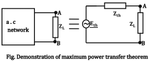
Depending nature of ZL and 2th, following are the possible cases and corresponding conditions for maximum power transfer,
(1) If Zth and ZL are resistive, ZL = Zth.
(2) If Zth and ZL are impedance, ZL= 
(3) If Zth is complex and ZL is resisitive, ZL = |Zth|.
(4) If ZL= RL + JXL such that XL is fixed and RL is variable, then, RL = |Zth + JXL|.
(5) If ZL = RL + JXL is such that RL is fixed and XL is variable, then XL = lm(Zth).
(6) If ZL = RL + JXL is such that 0 = tan-1 (XL/RL) is constant and  is varied, then |ZL| = |Zth|.
(7) For any arbitrary nature of ZL and Zth, appropriate value of ZL can be found using Lagrange's optimization.
Star-delta transformation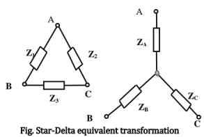

Polyphase Circuit Analysis
Single phase three wire system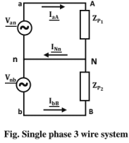
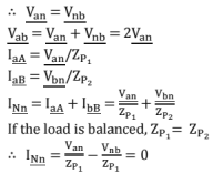
The wire nN is neutral wire. So if the load is balanced, current in neutral wire is zero. If the wires aA and bB have same impedance, still current in neutral wire is 0. If loads are unbalanced and Nn wire has some finite impedance, power dissipated in nN is finite.
Three phase source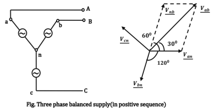
Consider a balanced supply as shown,
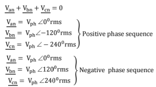
Three -phase Y-Y Connection including neutral (for balanced 3∅ supply)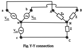

Let VL, 1L, Vph and lph stand for line voltage, line current, load voltage and load current.
If load is balanced, ZA = ZB = ZC = Zph∠∅
Power consumed by load = 

∴ If the load is balanced, neutral wire can be removed as  is zero.
If load is not balanced, 
Power consumed by load =  (if load is not balanced)
Three Phase Y - Δ Connection: (for balanced 3∅ supply)
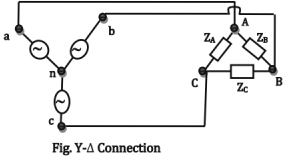
If the load is balanced, ZA = ZB = ZC = Zph ∠∅
Power consumed by load, P = √3 VLIL Cos∅
If the load is not balanced, Power consumed by load, P = 
Magnetically Coupled circuits
Two circuits are magnetically coupled, if operation of one circuit is effected by flux linkage due to coil in another circuit. In a magnetically coupled circuit, "Current entering dotted terminal of one coil will produce a voltage which is sensed positive at the dotted terminals of another coil and vice versa". So voltage across one coil depends not only on self inductance, but also on mutual inductance which gives extent of flux linkage between the two coils. Please note that dot convention doesn't make sense when it's associated with single coil.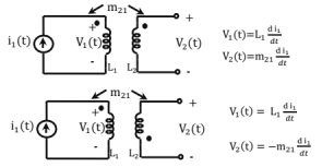
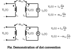
As the flux linkage in coil 1 due to the coil 2 is same as flux linkage in coil 2 due to coil 1, m12 = m21 = m
Also coefficient of coupling, K = m /  Here 0 ≤ K ≤ l ⇒ 0 ≤ m ≤
Co-efficient of coupling is in |0, 1| as flux linkage in one coil due to current in other coil will always be less than the flux produced by the same.

In frequency domain 
Instantaneous energy stored = 
Total energy stored = 


In frequency domain, 
Instantaneously energy stored 
Total energy stored = 
4. Transfer Function of an LTI System
Transfer function of a LTI system is defined as ratio of Laplace transform of output to the Laplace transform of input assuming initial conditions are zero. (LTI means linear and time- invariant)
If L{f(t)}=F(S), L{h(t)}=H(S) and L{g(t)}=G(S), G(S)=H(S) .F(S)
Transfer function of system, H(S) = 
Output response of a LTI system of transfer function, H(s)
Let the output response of a LTI system be defined as g(t) for a input f(t),
g(t) = gt(t) + gs(t)
where gt(t) is transient response of system and gs(t) is steady state response of system.
Let H(S) has poles at pi, i = 1; .......... n.
Here constant Ai can be found based on initial conditions. Above analysis can be used in R-L-C circuits to get voltage/current response at any time t.
Locus of phasors: Given any response G(S)P substitute S=σ+Jω to get generalized phasor of G(S). Locus of G(S) can be obtained by varying σ and ω. Thus the locus gives an idea about the phasor at different frequencies.
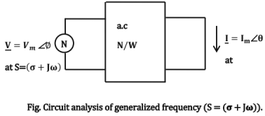
Circuit analysis at a generalized frequency: Any circuit can be generalized to operate at a frequency, S=σ+Jω. For dc signals, σ = 0 and ω = 0 and for ac signals, σ = 0. Let V(t) = Vmeσt.cos(ωt+∅) be the input to a network shown below and let the response be i(t) = Imeσtcos(ωt + θ). We see that  have a frequency of S = σ + Jω. In phasor form, the circuit can be represented as below,
5. Two Port Networks
Definitions: 'One port network" is a network which has a pair of terminals across which voltage can be applied and current can pass. 'T w o port network" is a network which has two pairs of terminals of above type. Let V = [V1 V2]T and I = [l1 I2]T be the voltages across and the currents through the two ports of the network.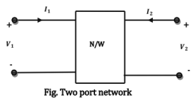
Z -Parameter (open circuit parameters or impedance parameters)
Y -Parameters (admittance parameter or short circuit parameter)
h - Parameters (hybrid parameters)
ABCD - Parameters (Transmission line or chain parameters)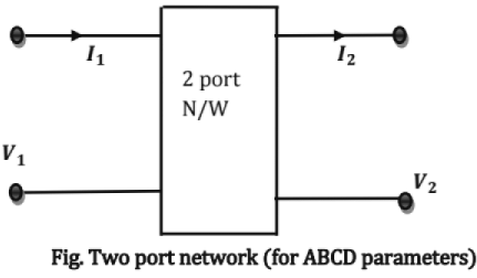

G-Parameters
Condition for reciprocity and symmetry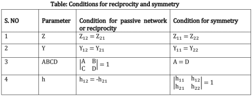
For converting one type of parameters to any other type, write equations to express relation between V1,l1, V2 & I2 in terms of given parameters and convert the same into the required form to get the target parameters.
Inter-connection of two port networks: If two 2-port networks A and B are connected in parallel, then Y-parameters of cumulative network is equal to sum of individual Y-parameters. If two 2-port networks A and B are connected in series, then Z parameters get added. If two 2-port networks A and B are connected in cascade, then ABCD parameters of cumulative network are equal to product of individual ABCD parameters.
6. Network Topology
Definitions
Graph: A network in which all nodes and loops are retained, but its branches are represented by lines.
- Voltage sources - replaced by short circuit.
- Current sources - replaced by open circuit.
Sub-graph: A sub graph is a subset of the original set of graph branches along with their corresponding nodes.
Tree: A connected sub-graph containing all nodes of a graph but no closed path. The branches of tree are called Twigs.
Co-tree: Complement of Tree is called as Co-tree. The branches of co-tree are called as Links.
Formula: L = B-N+l, where
L = No. of links of co-tree,
B = No. of branches of graph,
N = Total no of nodes in graph
Nodal Incidence Matrix
Definition: It is defined as a matrix which completely defines which branches are incident at which nodes and the corresponding orientation.
- Anxb= {ahk} is a matrix of dimension n x b, n = no. of nodes, b = no. of branches
- Rank of Incidence Matrix is n -1.
- Sum of elements of any column is zero
Akk = 1, if branch k is associated with node h and oriented away from node h
= - 1, if branch k is associated with node h and oriented towards node h
= 0, if branch k is not associated with node h
Applications in Network Theory: We can write KCL, using the nodal incidence matrix as follows:
Anxb lb = 0 where lb = [i1, i2, ... ib] is branch current vector
No. of trees = Det |AAT|
Reduced Incidence Matrix: When any node is taken as reference, then the voltages of other nodes can be measured with respect the assigned reference, in the Fig, taking node 4 as reference reduces the matrix, to Reduced Incidence Matrix, dimensions being (n-lxb).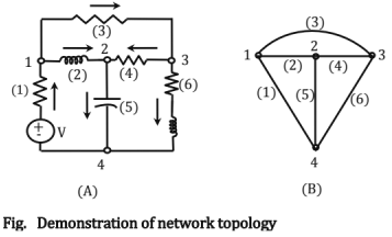
A = [At At]
Where At is a square matrix of order (n - 1) x (n - 1) and At is a matrix of order (n - l) x (b - n + 1) whose columns correspond to the links.
Loop Incidence Matrix (Fundamental Tie-set Matrix)
Definition: It is defined as the matrix representation in which the loop orientation is to be the same as the corresponding link direction.
Rank of B is b-n+1;
Steps to get this Matrix
- Draw the oriented graph of network. Choose a tree.
- Each link forms an independent loop & the direction of this loop is same as that of the corresponding link. Choose each link in turn.
- Prepare the tie-set matrix Bixb = {bhk}, 1 = no of loops, b = no of branches, defined as follows.
To write a Tie Set Matrix for Fig 1, steps have been stated schematically.
bkk = +1, if branch kis in loop h and their orientations coincide
= -1, if branch k is in loop h and their orientations do not coincide
= 0, if branch k is not in loop
Applications in Network Theory
We can write KVL, using the loop incidence matrix as follows
BixbVb = 0, where Vb = [v1, v2,--vb] is branch voltage vector
⇒ lb = [Bixb] T/l, where lt = [i1, i2,..il] is loop current vector
Fundamental Cut-Set Matrix: lt is defined as a set of branches whose removal cuts the connected graph into two parts such that the replacement of any one branch of the cutest renders the two part connected.
Rank of Q is n-1
Steps to get Cut-Set
- Draw the oriented graph of a network and choose a tree.
- For n-1 twigs, we will get n-1 cut sets will exist.
- Direction of cut-set is same as twigs. Choose each twig in turn to obtain the matrix.
- Prepare the cut set matrix Q(n-i)x b = {qij}, where n = no of nodes, b = no of branches as follows,
qtf = 1, if branch j is in the cut-set i, and the orientations coincide
= - 1, if branch j is in the cut-set i and the orientations do not coincide
= 0, if branch j is not in the cut-set i
Applications in Network Theory: From the cut-set matrix, we can write equations relating the branch voltages to the node voltages as follows, [Q(n-i)xb]Ib = 0 ⇒ Vb = [Q(n- i)xb]TVn-1
where Vn-i = [v1, v2,...vn-1] is node voltage vector
|
1 videos|30 docs|57 tests
|


